
Conductive electrode using metal oxide film with network structure of nanograins and nanoparticles, preparation method thereof and supercapacitor using the same

Active Publication Date: 2010-01-07
KOREA INST OF SCI & TECH
View PDF3 Cites 21 Cited by
  • Summary
  • Abstract
  • Description
  • Claims
  • Application Information

AI Technical Summary

Benefits of technology

[0016]There has been an increasing demand toward the development of a process enabling a simple large-scale production of ruthenium oxide with a network structure of ultrafine nanograins and / or nanoparticles generally having a size of 5 to 50 nm, preferably 5 to 30 nm. Therefore, an object of the present invention is to provide a conductive electrode using new improved porous conducting metal oxide and a high-speed, high-capacity supercapacitor using the electrode.
[0020]The porous conducting metal oxide film of the present invention, which has a network structure of ultrafine nanograins and / or nanoparticles with a size of 5 to 30 nm, has significantly improved specific surface area and superior electrical conductivity. An electrode prepared by forming a conducting metal oxide coating layer on the porous conducting metal oxide film is applicable particularly for electrode of supercapacitors, catalyst for DMFCs, sensor, insoluble oxide catalyst electrode, and the like. Further, adhesion between a current collector and the conducting metal oxide film layer is significantly improved through a heat compressing or hot pressing process, and it is possible to easily form a thick conducting metal oxide film layer by adjusting the spinning time.

Problems solved by technology

However when a template such as AAO is used, a good productivity cannot be attained.
Further, since the size of the ruthenium oxide nanowire is restricted by the size of the template, this method is not suitable for large-scale production in view of cost competitiveness and reproducibility.

Method used


Image

  • Conductive electrode using metal oxide film with network structure of nanograins and nanoparticles, preparation method thereof and supercapacitor using the same
  • Conductive electrode using metal oxide film with network structure of nanograins and nanoparticles, preparation method thereof and supercapacitor using the same
  • Conductive electrode using metal oxide film with network structure of nanograins and nanoparticles, preparation method thereof and supercapacitor using the same

Examples


example 1

Preparation of Ruthenium Oxide Nanofiber Network Through Preparation of Ruthenium Oxide Precursor-Polyvinyl Acetate Composite Fiber Layer and Post Heat Treatment

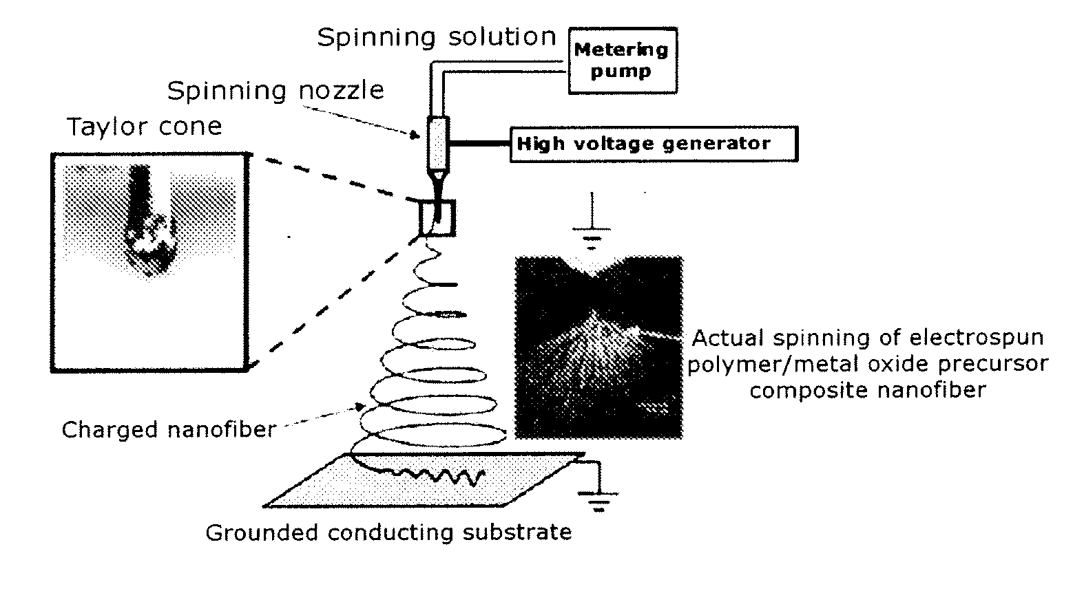
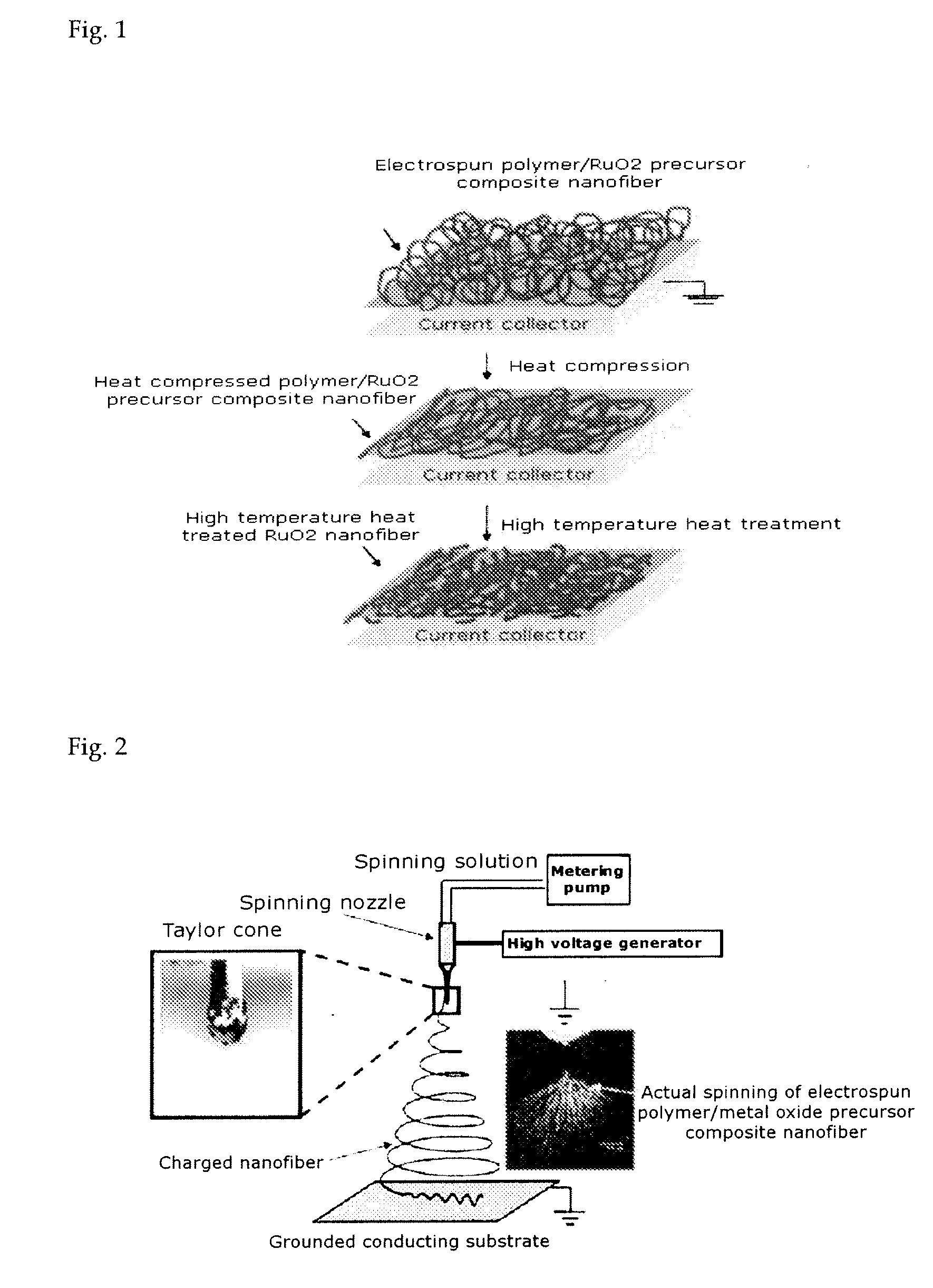
[0078]1.6 g of polyvinyl acetate (molecular weight: 1,000,000) was dissolved in 20 mL of dimethylformamide for about a day. 5 g of ruthenium(III) chloride hydrate (RuCl3-nH2O) was added to the resultant polymer solution and dissolved by mixing. Because ruthenium(III) chloride hydrate dissolves well in DMF, acetic acid may not be used for enhancing catalytic reaction. Following the reaction, the precursor was transferred to a syringe. The syringe was mounted on an electrospinning apparatus and a voltage was applied between the syringe tip and the current collector to prepare a ruthenium precursor-polyvinyl acetate composite fiber layer. Here, the applied voltage was 10 kV, flow rate was 5 μL / min, total ejection amount was 600 μL, and distance between the tip and the current collector was about 17.5 cm. In the ruthenium precur...

example 2

Preparation of Ruthenium Oxide Nanofiber Network Comprising Nanograins and / or Nanoparticles Through Heat Compression and Post Heat Treatment of Ruthenium Precursor-Polyvinyl Acetate Composite Fiber Layer

[0085]The ruthenium precursor / polyvinyl acetate composite fiber prepared in Example 1 was pressed using a lamination machine (120° C., pressing pressure: 0.1 MPa, pressing time: 90 seconds) and baked at 450° C. for 30 minutes to prepare a ruthenium oxide network comprising nanograins and / or nanoparticles. The surface structure varies depending on the pressing pressure and time. Further, the heat pressing temperature can be varied depending on the glass transition temperature of the polymer used. Especially, the size of nanograins can be easily controlled by controlling the heat treatment temperature.

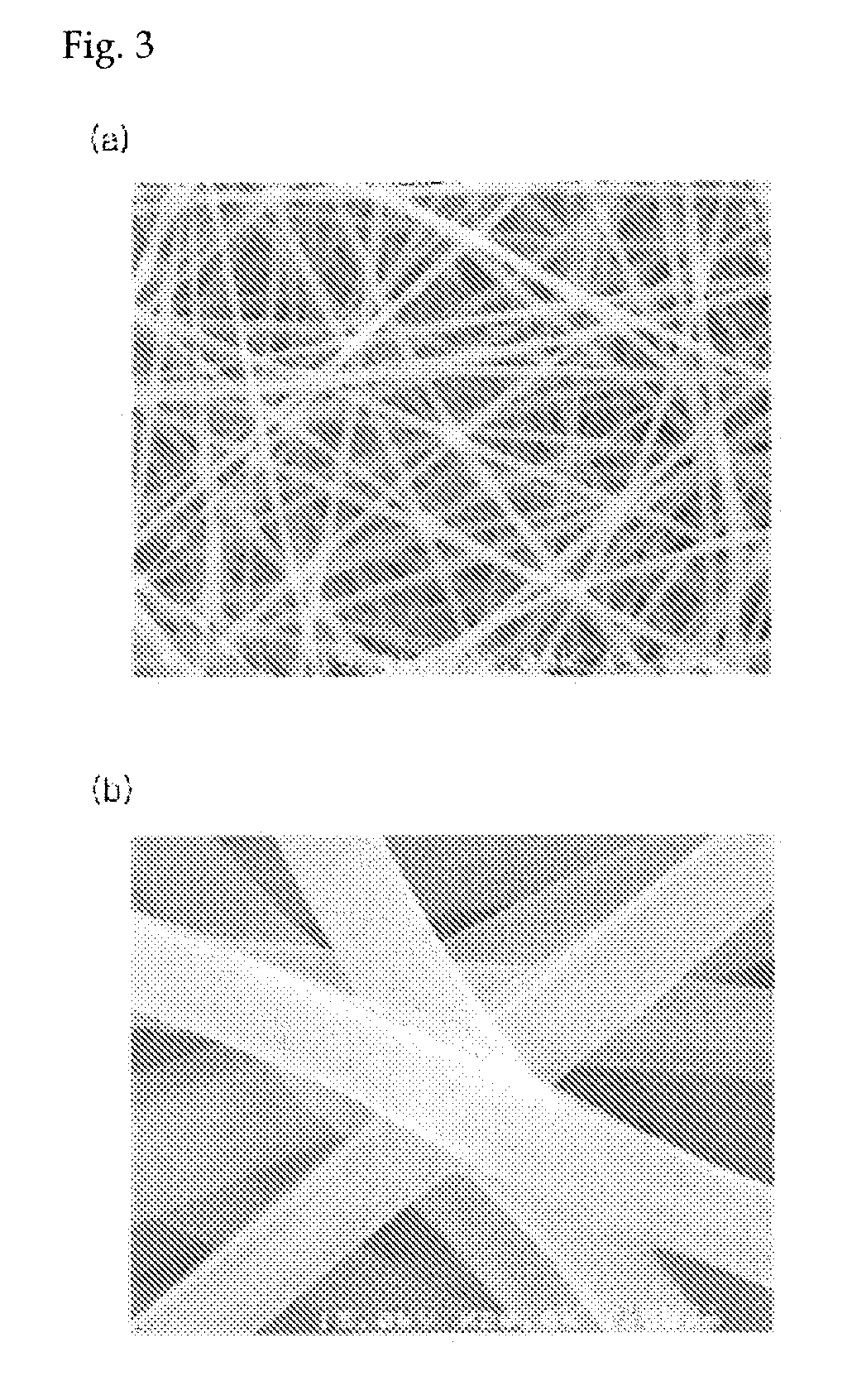
[0086]FIG. 8 shows an SEM image of a RuO2 / PVAc composite fiber prepared by electrospinning in accordance with the present invention, after heat compressing (120° C., 90 seconds, 0.1 MPa)....

example 3

Preparation of Iridium Oxide Nanofiber Network Comprising Nanograins and / or Nanoparticles Through Heat Compression and Post Heat Treatment of Iridium Precursor-Polyvinyl Acetate Composite Fiber Layer

[0093]In order to prepare conducting metal oxide IrO2 listed in Table 1, iridium(III) chlorite hydrate (298.56 g / mol) was dissolved in dimethylformamide (DMF). Polyvinyl acetate (PVAc, molecular weight: 500,000 to 1,000,000) was dissolved in the DMF solution of the iridium precursor. Following the reaction, the precursor was transferred to a syringe. The syringe was mounted on an electrospinning apparatus and a voltage was applied between the syringe tip and the current collector to prepare an iridium precursor-polyvinyl acetate composite fiber layer. Here, the applied voltage was 10 kV, flow rate was 5 μL / min, total ejection amount was 600 μL, and distance between the tip and the current collector was about 17.5 cm. In the iridium precursor-polyvinyl acetate composite fiber layer formed...


PUM

PropertyMeasurementUnit
Temperatureaaaaaaaaaa

Abstract

The present invention relates to a porous conducting metal oxide electrode prepared by depositing a porous conducting metal oxide film comprising a conducting metal oxide film layer having a network structure of nanofibers, comprising nanograins or nanoparticles, on at least one surface of a current collector, and a conducting metal oxide coating layer on the network layer of the porous conducting metal oxide through the constant current method or the cyclic voltammetric method, and a high-speed charge / discharge and ultrahigh-capacity supercapacitor using the porous conducting a metal oxide electrode.

Description

CROSS-REFERENCE TO RELATED APPLICATION[0001]This application claims under 35 U.S.C. §119(a) the benefit of Korean Patent Application No. 10-2008-0025996 filed Mar. 20, 2008, the entire contents of which are incorporated herein by reference.BACKGROUND OF THE INVENTION[0002]1. Field of the Invention[0003]The present invention relates to a porous conducting metal oxide electrode prepared by depositing a porous conducting metal oxide film comprising a conducting metal oxide film layer having a network structure of nanofibers, comprising nanograins or nanoparticles, on at least one surface of a current collector, and a conducting metal oxide coating layer on the network layer of the porous conducting metal oxide through the constant current method or the cyclic voltammetric method, and a high-speed charge / discharge and ultrahigh-capacity supercapacitor using the porous conducting metal oxide electrode. The capacitor electrode, with a metal oxide film layer deposited on a porous conductin...

Claims


Application Information

Patent Timeline
IPC IPC(8): H01G4/008B05D5/12
CPCH01G11/46Y02E60/13Y10T428/25Y10T29/417H01G11/28
Inventor KIM, IL DOOHONG, JAE-MINJO, SEONG MUKIM, DONG YOUNG
Owner KOREA INST OF SCI & TECH
Learn More