
Biomolecule sensor, method for manufacturing the same, biomolecule detection method, and biomolecule detection system

a biomolecule sensor and sensor technology, applied in the field of biomolecule sensor for detecting a biomolecule, can solve the problems of insufficient fixing stability of microparticles, inability to provide stable performance of devices, and difficulty in obtaining one-to-one correspondence between one pixel and a spatial arrangement of a dna molecule, so as to improve fluorescence detection sensitivity and improve reproducibility. the effect of detection accuracy

Inactive Publication Date: 2010-01-14
HITACHI HIGH-TECH CORP
View PDF11 Cites 16 Cited by
  • Summary
  • Abstract
  • Description
  • Claims
  • Application Information

AI Technical Summary

Benefits of technology

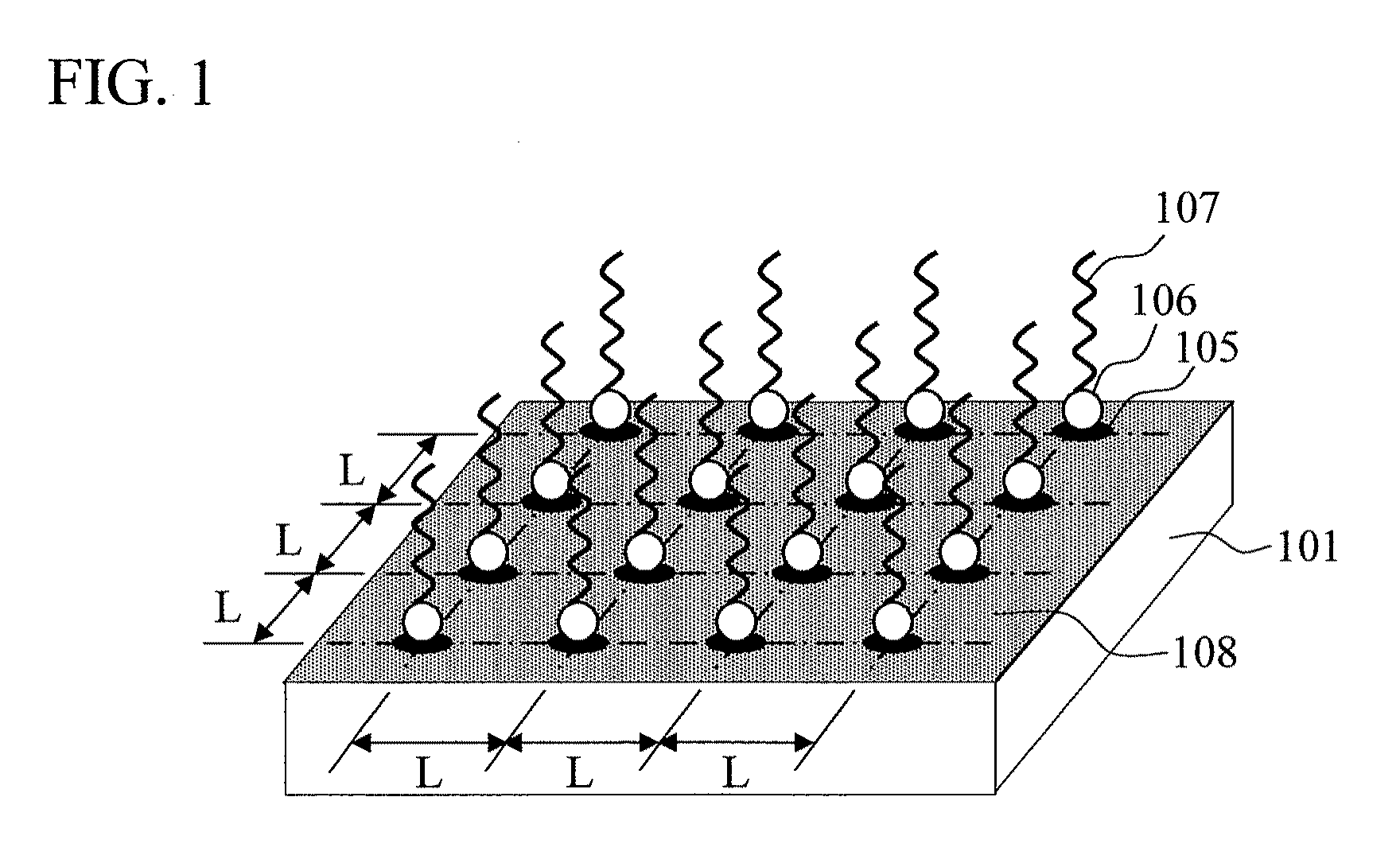
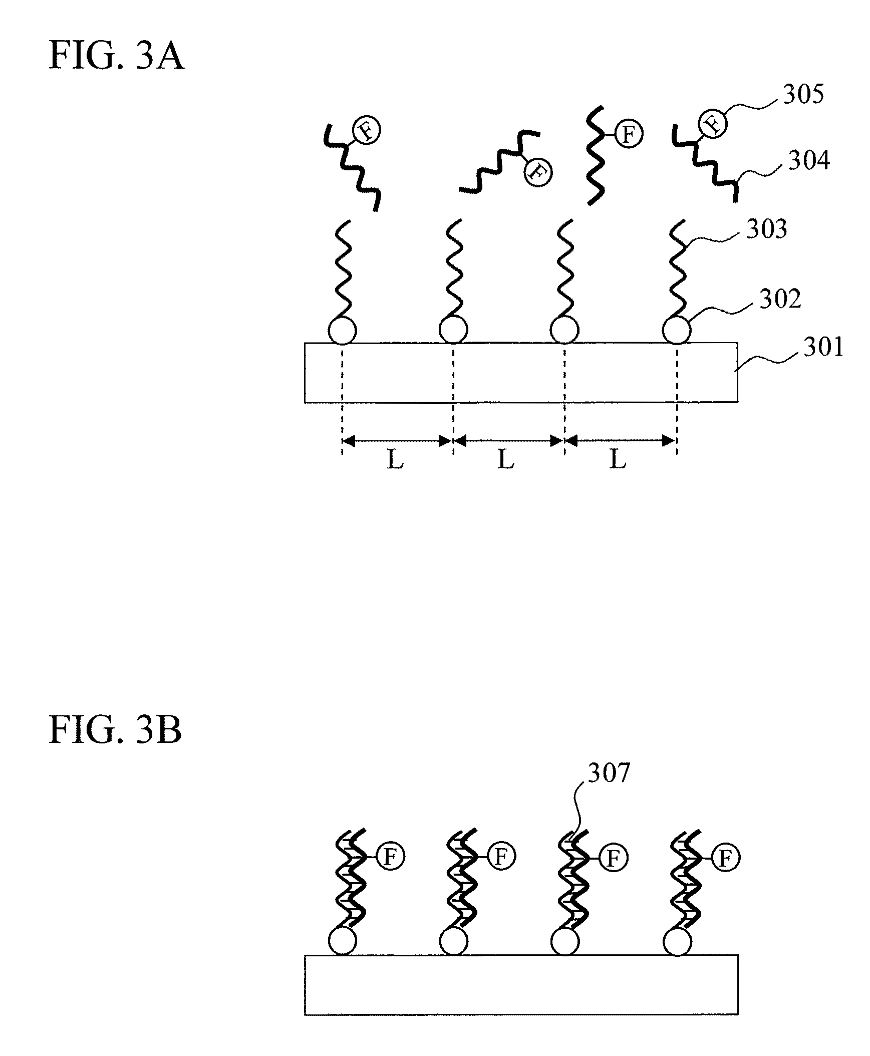
The present invention provides a biomolecule sensor with improved accuracy and reproducibility for detecting biomolecules, such as DNA molecules. The sensor consists of a carrier substrate with a grid dot pattern of linker molecules fixed on its surface. Metal microparticles are then fixed on the linker molecule dots, with one probe molecule fixed on each metal microparticle. The sensor can detect single molecules with high sensitivity and accuracy. The invention addresses the issues of low accuracy and reproducibility in biomolecule sensors and provides a solution for improving performance.

Problems solved by technology

Hence, it is difficult to obtain a one-to-one correspondence between one pixel and a spatial arrangement of a DNA molecule serving as a site for emitting fluorescence in a sequencing process.
In the method described in Non-patent Document 4, colloid microparticles are simply physically adsorbed on a surface, and such a state does not provide a sufficient stability of fixing for the microparticles.
Therefore, simply following the method cannot provide stable performance of a device even with the colloid microparticles indicating where single DNA molecules are located.
In the method described in Non-Patent Document 5, which only focuses on improving fluorescence detection sensitivity, a numerous number of probe molecules are fixed on silver nanoparticles; thus, there is a problem concerning the detection accuracy.
Although there are ideas for solving problems regarding low accuracy and low reproducibility of biomolecule sensors as described above, each one of the ideas does not provide any effective result.
The following points are the main causes for decreasing the accuracy and reproducibility.(1) The density of fixed probe molecules is not quantitatively controlled.(2) Distances among probe molecules are random, and the biomolecule detection reactions by the individual probe molecules are not independent but interfering with one another.(3) The residual biomolecules which are non-specifically adsorbed on the surface decrease accuracy of detection signals.

Method used


Image

  • Biomolecule sensor, method for manufacturing the same, biomolecule detection method, and biomolecule detection system
  • Biomolecule sensor, method for manufacturing the same, biomolecule detection method, and biomolecule detection system
  • Biomolecule sensor, method for manufacturing the same, biomolecule detection method, and biomolecule detection system

Examples


example 1

(Step 1) Coating Step of Positive-Type EB Resist on Substrate Surface: FIG. 11A

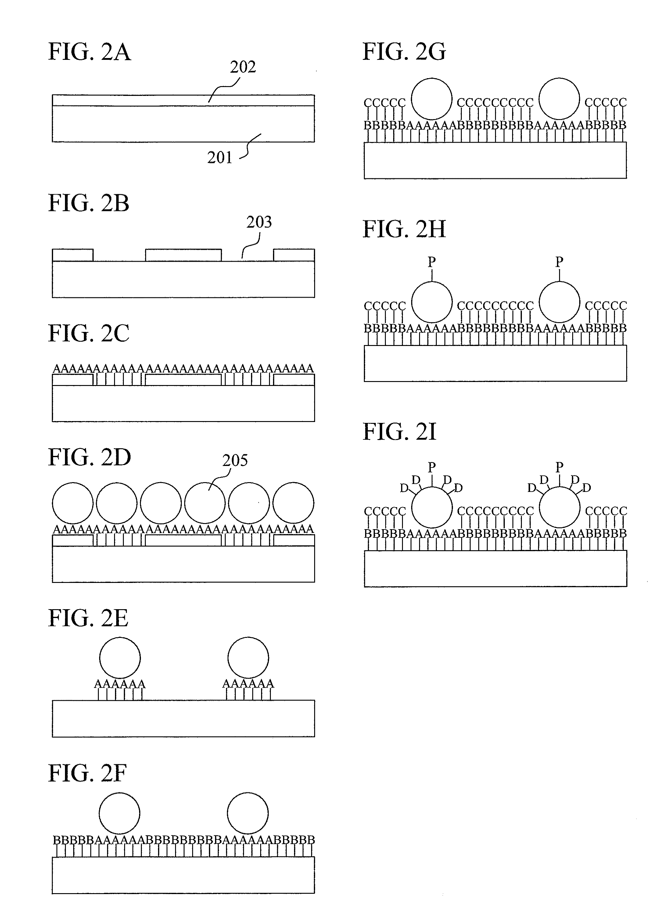
[0106]A Si substrate having a diameter of 4 inches (about 102 mm) provided with a highly flat thermally-oxidized film of 100 nm was used in the place of a carrier substrate 1101. The substrate was washed with a 0.1 wt % NaOH solution, further washed with a 0.1 wt % HCl solution, rinsed with pure water, and then dried. A main chain scission-type positive-type resist was used as the resist in this example. After being diluted with anisole, the resist was coated on the substrate using a spin coater. After coating, the substrate was baked at 180° C. in an N2 flow for 20 minutes for removal of the solvent. In this example, a resist film thickness of 60 nm, which is sufficiently thin and is not worn out by the EB processing, was adopted (resist:anisole=1:3 dilution). In order to prevent charging of the substrate during the EB lithography, a conductive polymer (polyisothianaphthene sulfonate) solution was coated...

example 2

[0124]In order to measure a concentration detection limit of DNA microarray, a gold nanoparticle grid array having single probe DNAs fixed thereon was prepared in the same methods described in Steps 1 to 9 in Example 1. Meanwhile, a conventional array was prepared similarly in the method described in Example 1. Hybridization was performed in Step 10 described in Example 1.

[0125]In this example, the amount of completely complementary target DNAs having fluorescent molecules bound thereto in the hybridization was varied in a range from 1 amol to 1 fmol. The relationship between the fluorescence intensity and the amount of target DNAs was investigated for each array. The result suggested, as shown in FIG. 16, that the gold nanoparticle grid array had improved detection sensitivity for target DNA compared to the conventional array. While the detection limit of the conventional array was 100 amol, the detection limit of the gold nanoparticle grid array was 1 amol; thus, the sensitivity w...

example 3

[0126]This example shows a case of using the present invention in DNA sequencing. A substrate for DNA sequencing was prepared according to Steps 1 to 8 described in Example 1 for the DNA sequencing. In this example, a quartz substrate was used in the place of the Si substrate. In the formation of openings by the EB lithography and development in Step 2, a pattern having openings of 40 nm φ arranged in a grid form at pitches of 1 μm was prepared. With this pattern, gold nanoparticles were aligned in the grid form at pitches of 1 μm. A scanning electron microscopic (SEM) observation result of the gold nanoparticle grid array substrate thus prepared is shown in FIG. 17. It was confirmed that the gold nanoparticles of 30 nm φ were aligned at pitches of 1 μm. Accordingly, if a CCD camera for detecting fluorescence intensity has a pixel size of 1 μm2, it is possible to detect a fluorescence signal from one DNA molecule with one pixel in the sequencing process. A fluorescence signal from a...


PUM

PropertyMeasurementUnit
particle sizeaaaaaaaaaa
thicknessaaaaaaaaaa
thicknessaaaaaaaaaa

Abstract

The present invention aims to improve detecting accuracy and reproducibility of a biomolecule sensor. The biomolecule sensor of the present invention includes single probe molecules orderly aligned and fixed on grid points on the surface of a substrate. Accordingly, in the biomolecule sensor of the present invention: probe molecules for detecting a biomolecule are orderly aligned and separately fixed; blocking for preventing non-specific adsorption is applied to a region other than the region of the probe molecules for detecting a biomolecule; and fluorescence enhancement is achieved by metal microparticles.

Description

CLAIM OF PRIORITY[0001]The present application claims priority from Japanese application JP 2007-24082 filed on Feb. 2, 2007, the content of which is hereby incorporated by reference into this application.BACKGROUND OF THE INVENTION[0002]1. Field of the Invention[0003]The present invention relates to a biomolecule sensor for detecting a biomolecule, a method for manufacturing a biomolecule sensor, a biomolecule detection method, and a biomolecule detection system.[0004]2. Description of the Related Art[0005]Having virtually completed the human genome deciphering, a large number of researchers have been actively conducting studies for elucidation of gene functions in recent years. In this research field where specific and exhaustive detection of genes and proteins in vivo is required, technological development for detection of genes and proteins has been extensively conducted all over the world. Meanwhile, techniques for identifying pathogens and viruses, which entered living organis...

Claims


Application Information

Patent Timeline
Patent Type & Authority Applications(United States)
IPC IPC(8): C40B30/04C40B40/00C40B40/06C40B50/14C40B60/10
CPCG01N21/6428G01N21/6452G01N33/582G01N33/54313G01N33/553G01N21/648
Inventor NAKAHARA, MIWAKOINOUE, TAKASHIKOGI, OSAMU
Owner HITACHI HIGH-TECH CORP
Learn More