Preparation of fuel usable in a fossil-fuel-fired system

a technology of fossil fuel and fuel, which is applied in the field of reducing emissions of fossil fuelfired systems, can solve the problems of reducing the performance of the esp, limiting the strength of the electrostatic field, and emitted high-polluting flue-gas streams into the atmosphere of fossil-fuel-fired furnaces, so as to reduce the opacity of the flue-gas, the effect of reducing the emission

Active Publication Date: 2010-02-04
EVONIK SUPERABSORBER LLC
View PDF57 Cites 10 Cited by
  • Summary
  • Abstract
  • Description
  • Claims
  • Application Information

AI Technical Summary

Benefits of technology

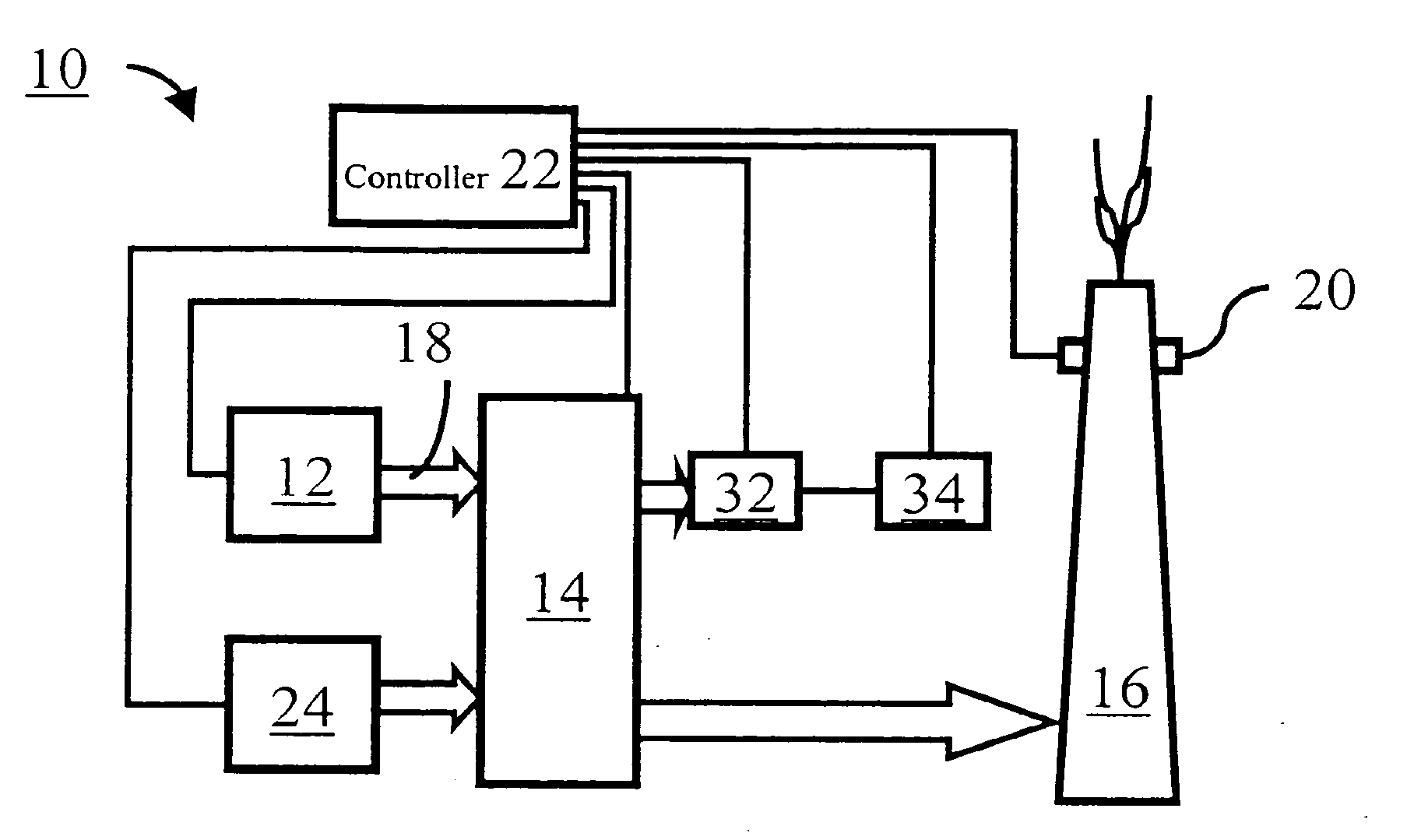
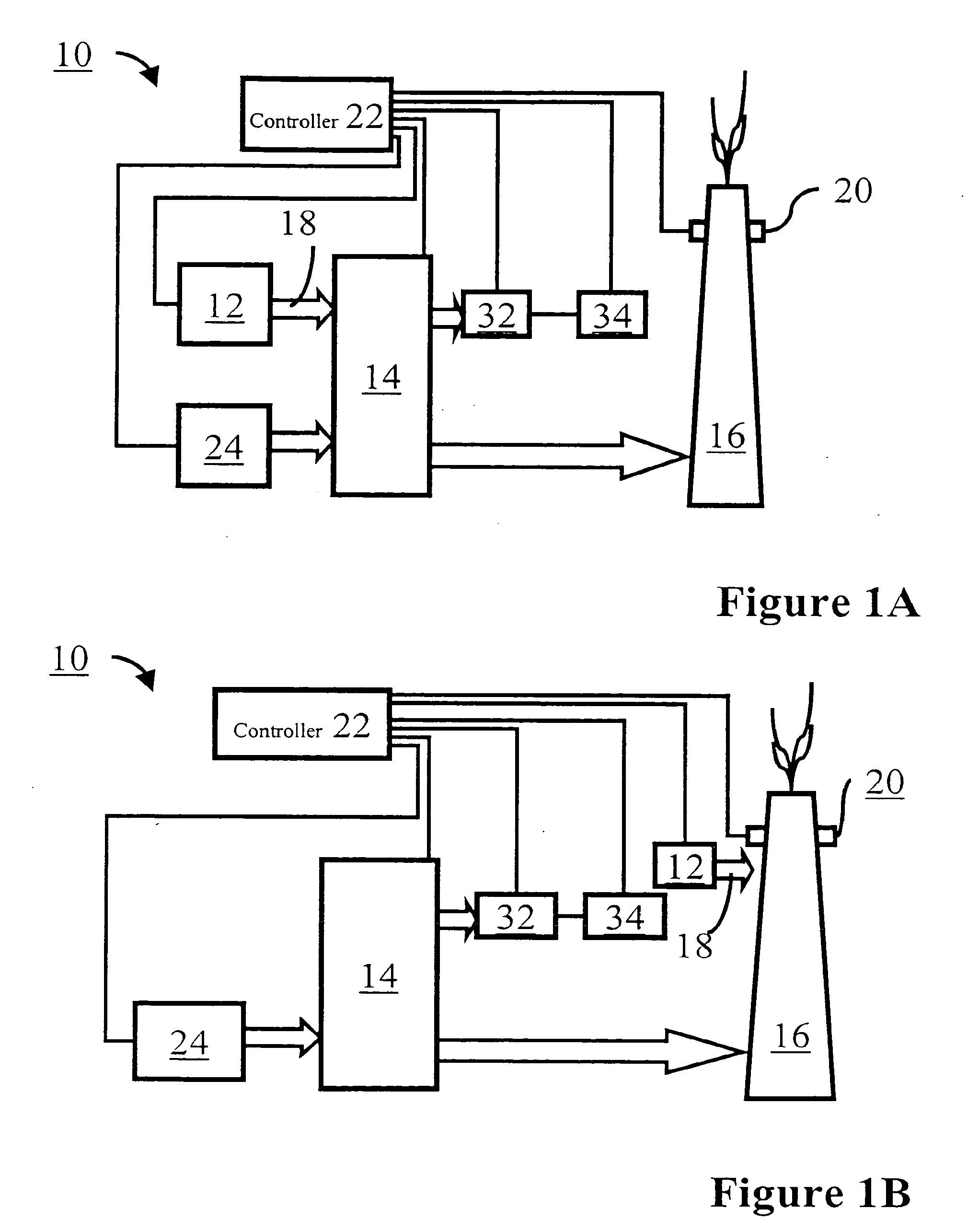
[0075]In an aspect, the present invention is to provide a fuel usable in a fossil-fuel-fired system 10 to control the emissions communicated by the fossil-fuel-fired system 10 into the atmosphere. The fuel includes at least one combustible material and an organic-emissions-control agent 18. The emission-control agent 18 is capable of interacting with one of the fuel, the combustion products of the fuel, and the fuel and combustion products so as to reduce the emission of at least one aspect of the flue-gas. In this manner, the emissions communicated by the fossil-fuel-fired system into the atmosphere are controlled.
[0076]In another alternative aspect, the present invention is to provide a fuel usable in a fossil-fuel-fired system 10 to control the opacity of the combustion products communicated by the fossil-fuel-fired system 10 into the atmosphere. The fuel includes at least one fossil fuel and at least one opacity-control agent. The opacity-control agent is capable of interacting with one of the fuel, the combustion products of the fuel, and the fuel and combustion products so as to reduce the opacity of the flue-gas communicated by the fossil-fuel-fired system into the atmosphere. In this manner, at least the opacity of the flue-gas communicated by the fossil-fuel-fired system into the atmosphere is controlled.
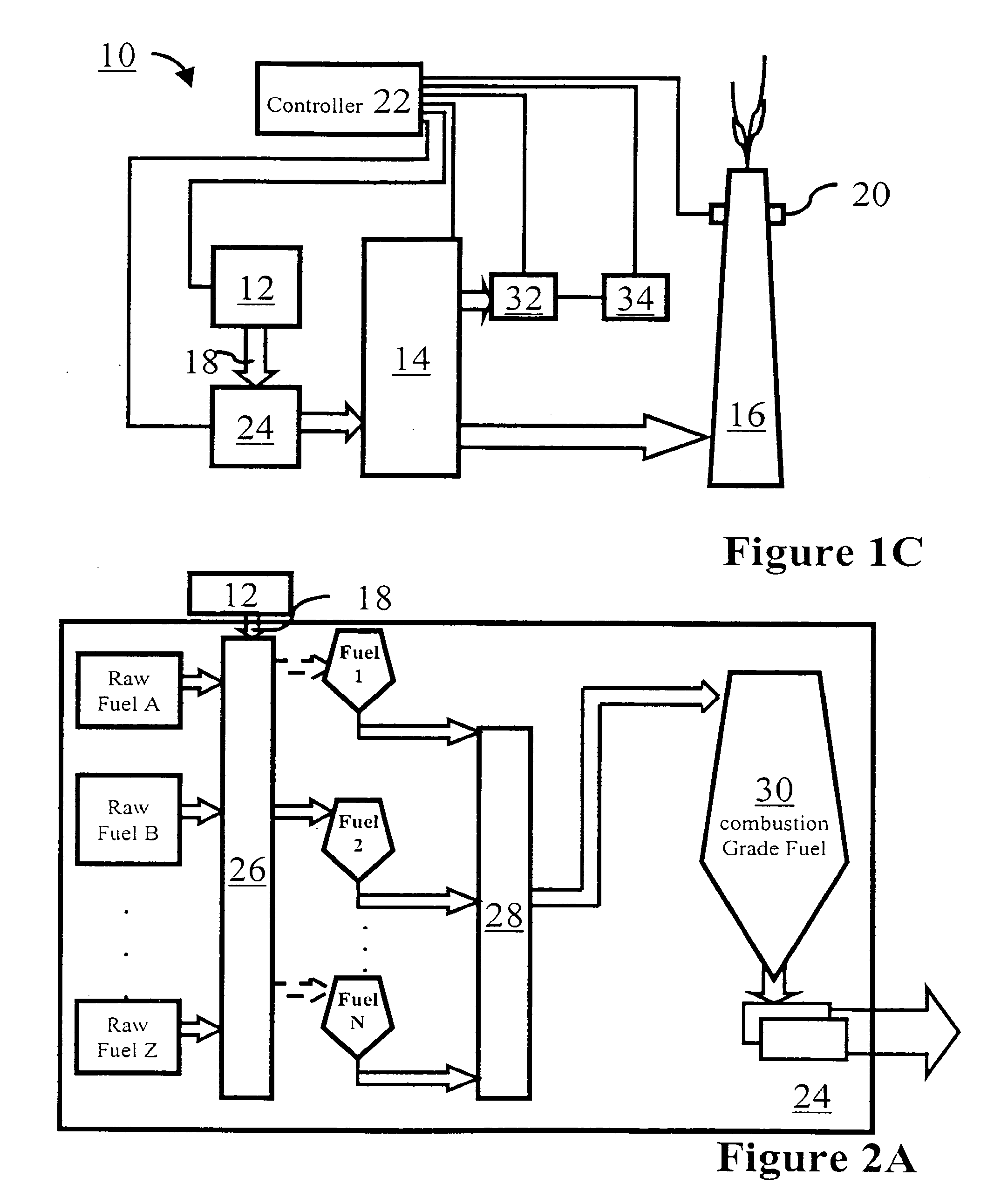
[0077]An operation of the fossil-fuel-fired system 10 is discussed with reference to FIG. 4, which is a schematic showing an integration of a fuel-preparation system 24 including a raw-fuel-fuel preparation system 26 and a refined-fuel-preparation system 28, a furnace 14 and an exhaust 16. A plurality of emissions-control-agent dispensers 12 are shown. The operation is discussed in the context of a coal-fired system.
[0078]Raw coal from a number of sources is processed through a dryer and crusher system (raw-fuel preparation system 26). During this processing and transport, an organic-emissions-control agent 18 may be added to the coal using a dispenser 12. Also, the coal from a number of sources may be blended by proportionally drawing coal from the number of sources simultaneously. The crushed coal is delivered to one or more bunkers. (Only one bunker is depicted in FIG. 4.)
[0079]The refined coal from the number of bunkers is processed through a pulverizing system (refined-fuel preparation system 28). During this processing and transport, if not already so done, or if additional amounts would beneficial, an organic-emissions-control agent 18 may be added to the coal using a dispenser 12′. Also, the refined coal from the number of bunkers may be blended by proportionally drawing crushed coal and / or other fuel such as, for example, petroleum coke, from the number of bunkers simultaneously. The pulverized coal is delivered to one or more bins. (Only one bin is depicted in FIG. 4.)
[0080]The pulverized coal from the number of bins is fed through a number of burners to the furnace 14. If not already so done, or if additional amounts would beneficial, an organic-emissions-control agent 18 may be added to the furnace 14 using a dispenser 12″.

Problems solved by technology

These fossil-fuel-fired furnaces, however, emit highly polluting flue-gas streams into the atmosphere.
A layer of particulates formed on the conductors limits the strength of the electrostatic field and reduces the performance of the ESP.
However, positioning a wet ESP field upstream of a dry ESP field, such as that disclosed in U.S. Pat. No. 2,874,802, does not sufficiently remove contaminants from a flue-gas stream or address the above-described problems.
The '343 and '781 patents further teach that the use of absorbent particles as low as 50 μm or less is therefore generally undesirable, but a tendency with the use of larger particles, e.g., 200 μm and above, is that their rate of absorption of liquid from the environment can be rather slow and, if such particles aggregate, then the aggregates are rather large, and this can be undesirable.

Method used


Image

  • Preparation of fuel usable in a fossil-fuel-fired system
  • Preparation of fuel usable in a fossil-fuel-fired system
  • Preparation of fuel usable in a fossil-fuel-fired system

Examples


example 1

[0083]The superabsorbent is applied to coal prior to processing the coal by a ball mill to have a size of 1 to 10 mm. The mix is pulverized and carried, entrained in air from the pulverizes, as a fuel into the combustion chamber of a power station boiler. There is no evidence of clogging of the pulverizer or other parts of the apparatus through which the product travels from the mixer to the boiler. It was found that the emissions of the boiler were reduced.

example 2

[0084]A pilot test was performed at Hoosier Energy REC, Inc.'s Ratts Generating Station in Pike County, Indiana. The coal-fired facility is able to produce 250,000 kilowatts of electricity with twin turbine generators. The generating station is equipped with environmental controls and monitors; these include precipitators for the removal of flyash. Most of the fuel for the facility is Indiana coal with moderate sulfur content burned at about 12,000 BTU per pound and mined within a radius of 20 miles of the generating station.

TABLE 5ENVIROSORB 1880 Technical DataRetention Capacity (Test Method Nr. Q3T013):28.5-35.0g / gAbsorbency Under Load, [0.9 psi] (Test18.0g / g min.Method Nr. Q3T027):Particle Size: 100-850 microns (TestMethod Nr. Q3T015)% on 20 Mesh [850 μm]2.0%Max.% on 50 Mesh [300 μm]95%Max.% on 100 Mesh [150 μm]30%Max.% thru 100 Mesh [150 μm]3%Max.Apparent Bulk Density (Test530-725g / lMethod Nr. Q3T014):Moisture Content (Test Method Nr. Q3T028):5.0%MaxResidual Monomer (Test Method...


PUM


Abstract

A fossil-fuel-fired system, which includes an emissions-control-agent dispenser, a furnace, an emissions monitor and, optionally, a controller, is disclosed. The emissions-control-agent dispenser provides a prescribed amount of organic-emissions-control agent, such as, for example, an opacity-control agent to the fossil-fuel-fired system. The furnace includes an exhaust communicating with the atmosphere. The emissions monitor is capable of measuring at least one property of the flue-gas communicated through the exhaust to the atmosphere. For example, when an organic-emissions-control agent is an opacity-control agent, the emissions monitor has the capability of at least measuring opacity. When included, the controller communicates with at least the emissions-control-agent dispenser and the emissions monitor.

Description

PRIORITY APPLICATION[0001]This application claims priority to U.S. Patent Application Ser. No. 60 / 462,552 filed Apr. 11, 2003 entitled “Superabsorbent Polymer For Fossil-Fuel Incinerator Applications” and is incorporated in its entirety herein by reference.FIELD OF THE INVENTION[0002]The invention relates to a reduced-emissions fossil-fuel-fired system such as a fossil-fuel-fired furnace. In particular, the present invention is directed to reduce at least the opacity of the emissions from a fossil-fuel-fired system.BACKGROUND OF THE INVENTION[0003]The 1990 amendments to the United States Clean Air Act require major producers of air emissions, such as electrical power plants, to limit the discharge of airborne contaminants emitted during combustion processes. In most steam power plants in operation today, fossil fuels (such as petroleum or coal) are burned in a furnace including a boiler to heat water into steam. The steam drives turbines coupled to a generator to produce electricity...

Claims


Application Information

Patent Timeline
Patent Type & Authority Applications(United States)
IPC IPC(8): F23B90/00F23J7/00F23J15/00F23K3/00F23N5/08
CPCF23K2201/501F23K2201/505F23K2203/104F23K2203/201F23N5/082F23K2201/101C10L10/02F23J7/00F23J15/003F23K3/00F23K2201/10F23N2021/00F23N2221/00
Inventor ALLEN, GARY W.JOYCE, JR., JOHN T.
Owner EVONIK SUPERABSORBER LLC
Why Eureka
Try Eureka