Cardiovascular Devices and Methods

a technology of cardiac valves and valves, applied in the field of medical devices, can solve the problems of multiple valve devices that require a significant amount of time for inflation/filling, balloon deployment, and balloon deflation/unloading, and achieve the effects of reducing the incidence of dissection, and reducing the elastic recoil of the wall

Inactive Publication Date: 2010-02-11
ARTEMIS MEDICAL
View PDF68 Cites 34 Cited by
  • Summary
  • Abstract
  • Description
  • Claims
  • Application Information

AI Technical Summary

Benefits of technology

[0086]As mentioned above, the texture of the braid over the angioplasty balloon will create tiny micro-fractures within the plaque matrix which will reduce damage to the vessel wall, diminish the incidence of dissections, diminish the elastic recoil of the wall, and allow for more uniform compressibility of the plaque. All of these factors have been implicated in the re-stenosis process. This action, even without the drug delivery features, may diminish re-stenosis. However, by cre...

Problems solved by technology

Advantages of the LIS approach (over conventional surgery) are significant from a cost as well as a patient care and recovery point of view.
In and of itself, this technique as well as other inventions have tried to accomplish the same, but have been met with limited success.
However, the resulting multiple balloon device is more than complicated and Hegde et al. disclose a method for a complex and expensive device.
Further, using balloons for dilatation and for stent deployment require a significant amount of time for inflation/filling and subsequent deflation/un-filling of the balloons.
However, in addition to the inflation and deflation times mentioned above, the device described in this patent has the obvious drawbacks of requiring a separate lumen for each balloon.
In addition to increasing the cost of manufacture, this requirement requires the overall diameter of the catheter to be increased.
Marin and Marin indeed describe an alternative mechanical linkage device for stent deployment in these subsequent patents, however again only at the cost of losing cost effectiv...

Method used


Image

  • Cardiovascular Devices and Methods
  • Cardiovascular Devices and Methods
  • Cardiovascular Devices and Methods

Examples


Embodiment Construction

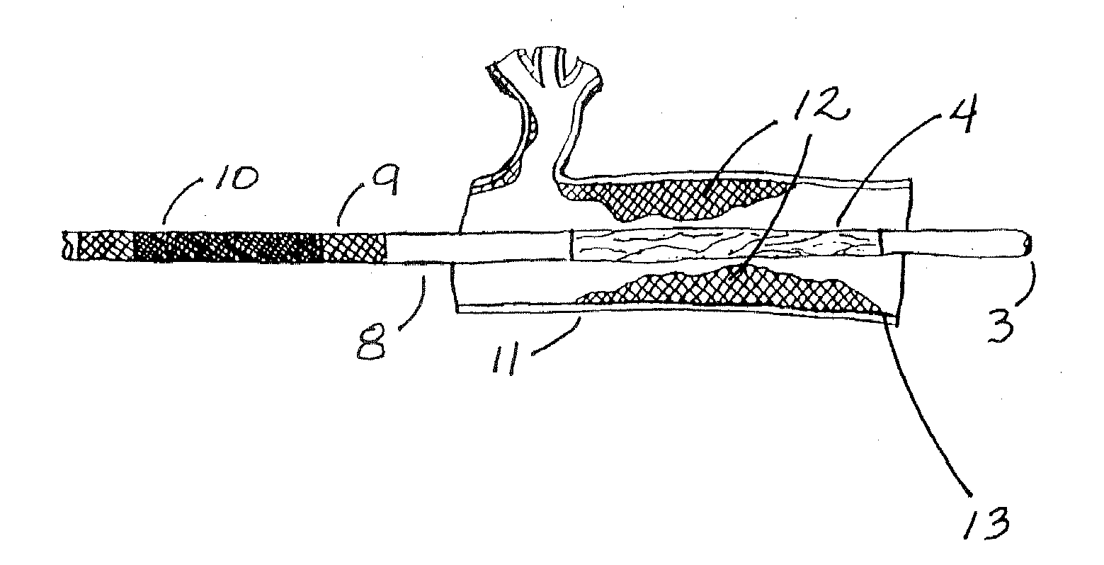
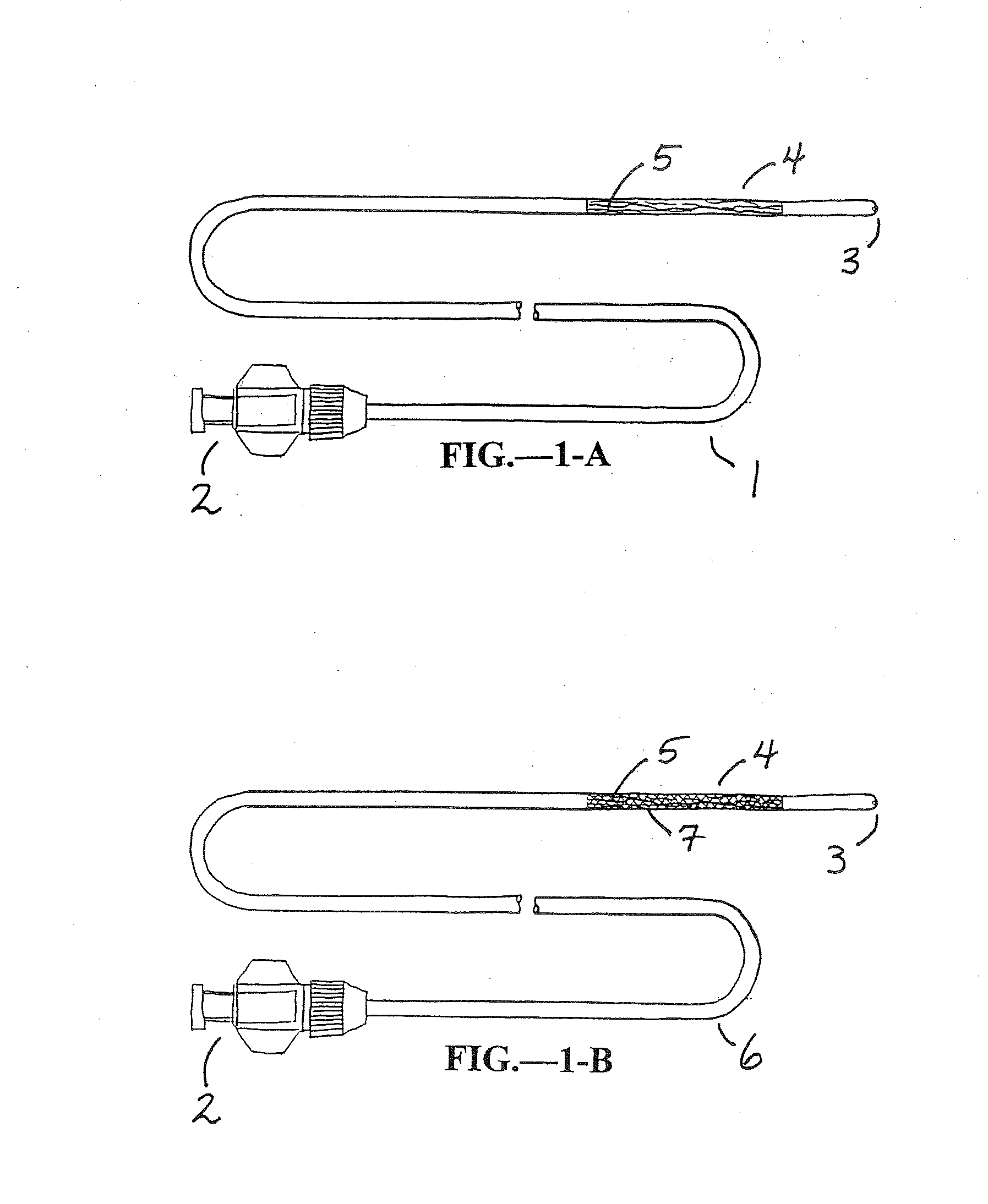
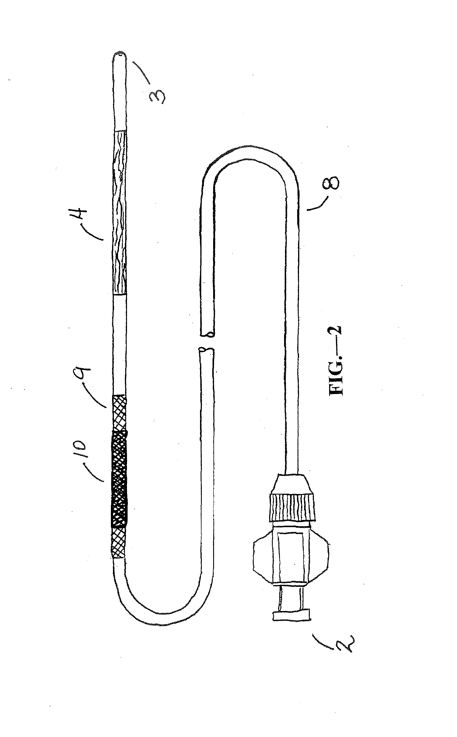
[0047]A The present invention is used for intervention into the tubular channels (arteries, veins, biliary tract, urological tract, gastro-intestinal tract, stents, grafts, sinuses, nasopharynx, heart, ears, etc.) or hollow cavities (stomach, gall bladder, urinary bladder, peritoneum, etc.) of the body. Further, it may be used in iatrogenically created passageways. It is particularly convenient to use in an environment of an operating room, surgical suite, interventional suite, Emergency Room, patient's bedside, etc. One preferred embodiment of this device is that the elongate, flexible shaft is inserted into the tubular channel or hollow cavity of the body usually through percutaneous access or via a surgical incision. In the case of lumens that enter and exit the body naturally, the device may enter through one of those entry or exit paths (i.e. rectal opening, mouth, ear, etc.). Once the device is in the preferred location (that being where the narrowing or obstruction is located...


PUM


Abstract

A material in a flowable state is applied to the interstitial pores of a radially-expandable endovascular tubular braid structure to modify the tubular braid structure for use in the treatment of cardiovascular disease. The material is cured to form a membrane at least within the coated interstitial pores. A cardiovascular device, for use in a vascular lumen within a body for treatment of cardiovascular disease, includes a braided body with electroporation means for helping prevent restenosis in a cardiovascular lumen. A method for treating cardiovascular disease includes placing a radially expandable and collapsible medical device within a cardiovascular passageway, positioning it at a target site, and placing it in a radially expanded state. Restenosis at the target site is inhibited by a chosen one of electroporation and iontophoresis. The medical device is collapsed and is then removed from the passageway.

Description

CROSS-REFERENCE TO RELATED APPLICATIONS[0001]This application is a is a continuation in part of U.S. patent application Ser. No. 11 / 143,396 filed Jun. 2, 2005, which division of U.S. patent application Ser. No. 09 / 781,721 filed on Feb. 12, 2001, which is a division of U.S. patent application Ser. No. 09 / 298,279 filed Apr. 23, 1999, which claims the benefit of the following provisional patent applications: application Ser. No. 60 / 083,178 filed Apr. 27, 1998; application Ser. No. 60 / 095,106 filed Aug. 3, 1998; and application Ser. No. 60 / 115,548 filed Jan. 12, 1999, the disclosures of which are incorporated herein by reference.[0002]This application is a continuation in part of U.S. patent application Ser. No. 11 / 776,257 filed Jul. 11, 2007, which is a continuation of U.S. patent application Ser. No. 10 / 866,980 filed Jun. 14, 2004, which is a continuation of U.S. patent application Ser. No. 10 / 051,848 filed Jan. 17, 2002, now abandoned, which is a continuation of U.S. patent applicati...

Claims


Application Information

Patent Timeline
IPC IPC(8): A61F2/06B05D3/10A61F2/90
CPCA61F2/90A61F2/958A61F2002/072A61F2250/0067A61L29/16A61L2300/416A61N1/327A61M29/02A61M2025/0057A61M2025/105A61M2025/1052A61M2025/1081A61N1/306A61M25/10
Inventor DUBRUL, WILLIAM R.FULTON, III, RICHARD EUSTIS
Owner ARTEMIS MEDICAL
Why Eureka
Try Eureka