Plasma display panel including frameless EMI filter, and/or method of making the same

a technology of plasma display panel and frameless emi filter, which is applied in the field of plasma display panel, can solve the problems of adversely affecting human bodies, increase in electromagnetic wave radiation, near-infrared emission, etc., and achieves superior display capabilities, easy manufacturing, and large screen

Active Publication Date: 2010-02-25
GUARDIAN GLASS LLC
View PDF21 Cites 66 Cited by
  • Summary
  • Abstract
  • Description
  • Claims
  • Application Information

AI Technical Summary

Benefits of technology

[0003]Image display devices are being widely used in a variety of applications, including TV screens, monitors of personal computers, etc. The plasma display panel (PDP) is gaining popularity as a next-generation display device to replace the CRT because a PDP is thin and a large screen can be readily fabricated with a plurality of units. A PDP includes a plasma display panel on which an image is displayed using a gas discharge phenomenon, and exhibits superior display capabilities, including high display capacity, high brightness, high contrast, clear latent image, a wide viewing angle, etc. In a PDP apparatus, when a direct current (DC) or alternating current (AC) voltage is applied to electrodes, a discharge of gas plasma is created, resulting in the emission of ultraviolet (UV) light. The UV emission excites adjacent phosphor materials, resulting in electromagnetic emission of visible light. Despite the above advantages, PDPs face several challenges associated with driving characteristics, including an increase in electromagnetic wave radiation, near-infrared emission, and phosphor surface reflection, and an obscured color purity due to orange light emitted from helium (He), neon, or xenon (Xe) used as a sealing gas.
[0007]In view of the above, there exists a need in the art for an improved PDP filter which is improved (with respect to conventional PDP EMI filters) with respect to one or more of: (i) improved chemical durability, (ii) improved thermal stability (e.g., upon optional heat treatment such as tempering), (iii) improved visible transmission, and / or (iv) improved EMI shielding properties.
[0012]To increase the yield of the coating process, various cut glass sheets may be arranged on the conveyor in close relative proximity to one another in order to attempt to fill up the area on the conveyor. In other words, cut glass sheets may be placed on a conveyor so as to approximate a large, un-cut glass sheet that would otherwise occupy substantially the entire bed size of the conveyor. Unfortunately, this compromise approach often takes time and / or significant manual effort, related at least in part to the careful arrangement of the cut glass sheets. Even with the attempted maximization of space, sputtered material is often wasted. Additionally, because the sheets oftentimes are small compared to bulk non-cut sheets, some sizes cannot be coated at all, while others inadvertently fall through rollers provided on the assembly line or are otherwise damaged or destroyed during the coating process.
[0014]In certain example embodiments of this invention, a plasma display panel (PDP) includes a filter supported by a glass substrate for blocking / shielding substantial amounts of electromagnetic waves, with the filter being supported by a side of the substrate opposite a viewer. A black frit and a silver frit comprise a filter frame and are supported by the filter such that the filter is closer to the glass substrate than either or both of the frits. The filter has high visible transmission, and is capable of blocking / shielding electromagnetic waves. In certain example embodiments, a silver based coating of the EMI filter reduces damage from EMI radiation through highly conductive Ag layers, blocks significant amounts of NIR and IR radiation from outdoor sunlight to reduce PDP panel temperature, and enhances contrast ratio through reduced reflection, while maintaining high visible transmission. In certain example embodiments, the filter is a TCC filter. Advantageously, a TCC may be coated on a stock, non-cut glass sheet.

Problems solved by technology

Despite the above advantages, PDPs face several challenges associated with driving characteristics, including an increase in electromagnetic wave radiation, near-infrared emission, and phosphor surface reflection, and an obscured color purity due to orange light emitted from helium (He), neon, or xenon (Xe) used as a sealing gas.
Some believe that the electromagnetic waves and near-infrared rays generated in PDPs may adversely affect human bodies and cause malfunctions of precision machines such as wireless telephones or remote controllers (e.g., see U.S. 2006 / 0083938, incorporated herein by reference).
Although the metal mesh-pattern filter exhibits a good electromagnetic wave shielding effect, it has several disadvantages including poor transmittance, image distortion, and an increase in the production cost due to a costly mesh.
However, conventional PDP EMI filters tend to lack durability and / or can stand to be improved upon with respect to visible transmission and / or shielding properties.
The use of such high temperatures (e.g., for 5-10 minutes or more) often causes coatings to break down and / or causes one or more of the aforesaid desirable characteristics to significantly deteriorate in an undesirable manner.
Conventional PDP EMI filters tend to suffer from a lack of thermal stability and / or durability upon heat treatment (HT).
In particular, heat treatment tends to cause conventional PDP filters to break down.
For example, the process described above often leads to a significant amount of waste and / or presents challenges when the TCC is applied.
Unfortunately, the above-described process requires coating cut glass sheets.
These cut glass sheets do not occupy the full dimensions of a typical conveyor or bed size, which leads to at least some of the problems noted below and / or presents other challenges.
Unfortunately, this compromise approach often takes time and / or significant manual effort, related at least in part to the careful arrangement of the cut glass sheets.
Even with the attempted maximization of space, sputtered material is often wasted.
Additionally, because the sheets oftentimes are small compared to bulk non-cut sheets, some sizes cannot be coated at all, while others inadvertently fall through rollers provided on the assembly line or are otherwise damaged or destroyed during the coating process.
Unfortunately, however, the screen printing of the conductive frit on the glass adds process steps, increases manufacturing costs, and reduces manufacturing yield, e.g., for the reason described above.

Method used


Image

  • Plasma display panel including frameless EMI filter, and/or method of making the same
  • Plasma display panel including frameless EMI filter, and/or method of making the same
  • Plasma display panel including frameless EMI filter, and/or method of making the same

Examples


Embodiment Construction

[0055]Referring now more particularly to the accompanying drawings in which like reference numerals indicate like parts / layers throughout the several views.

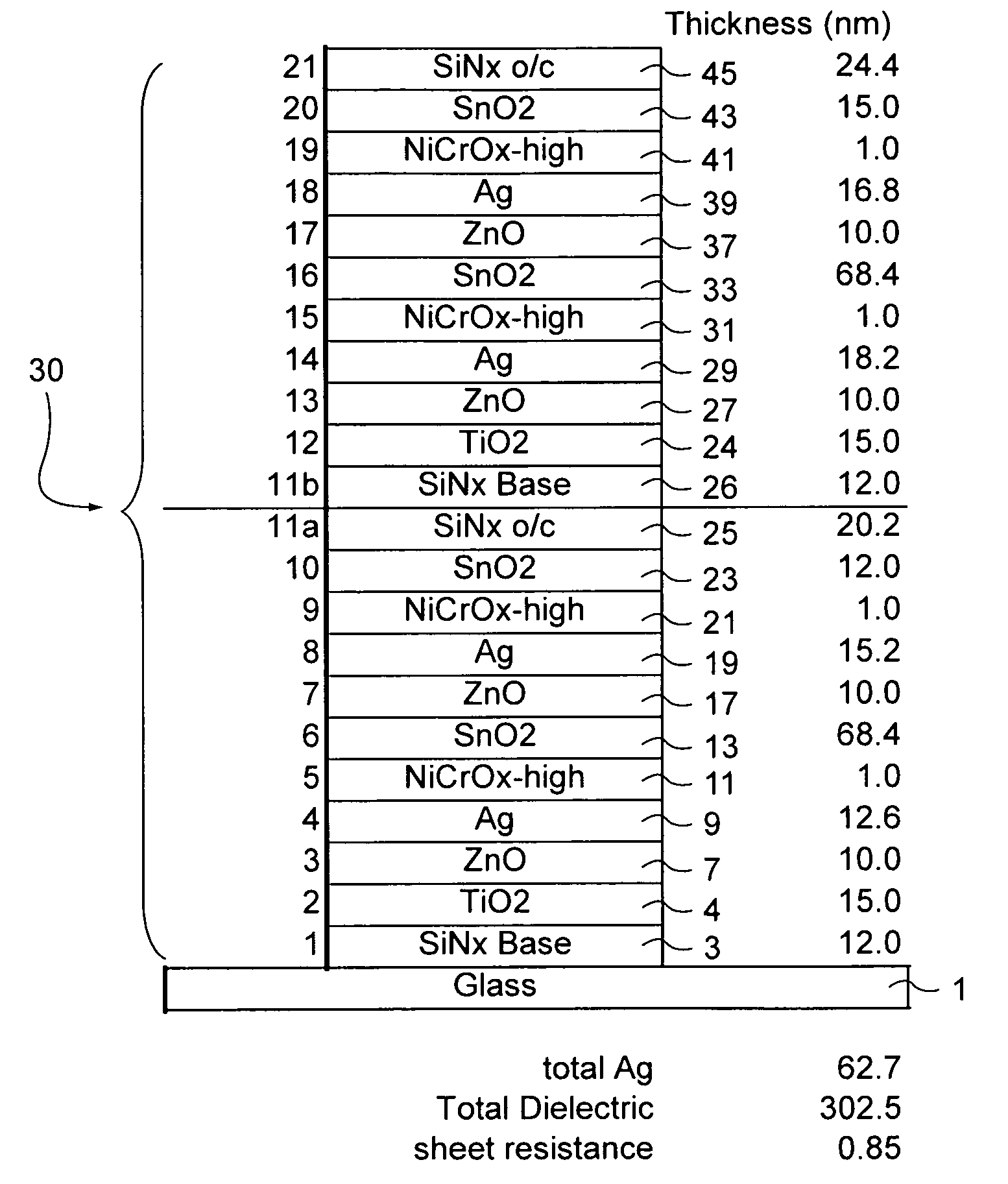
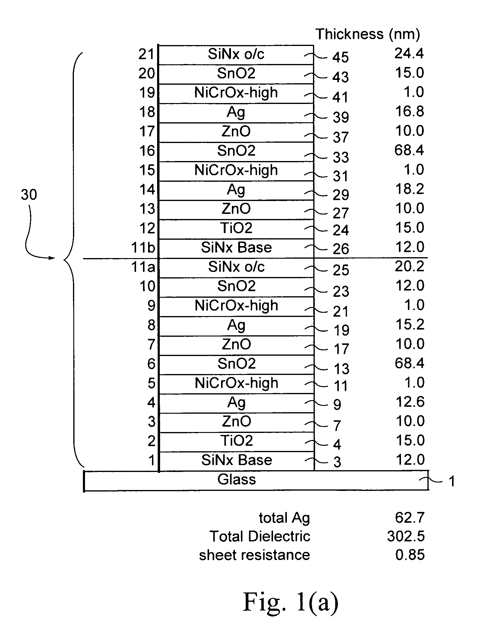
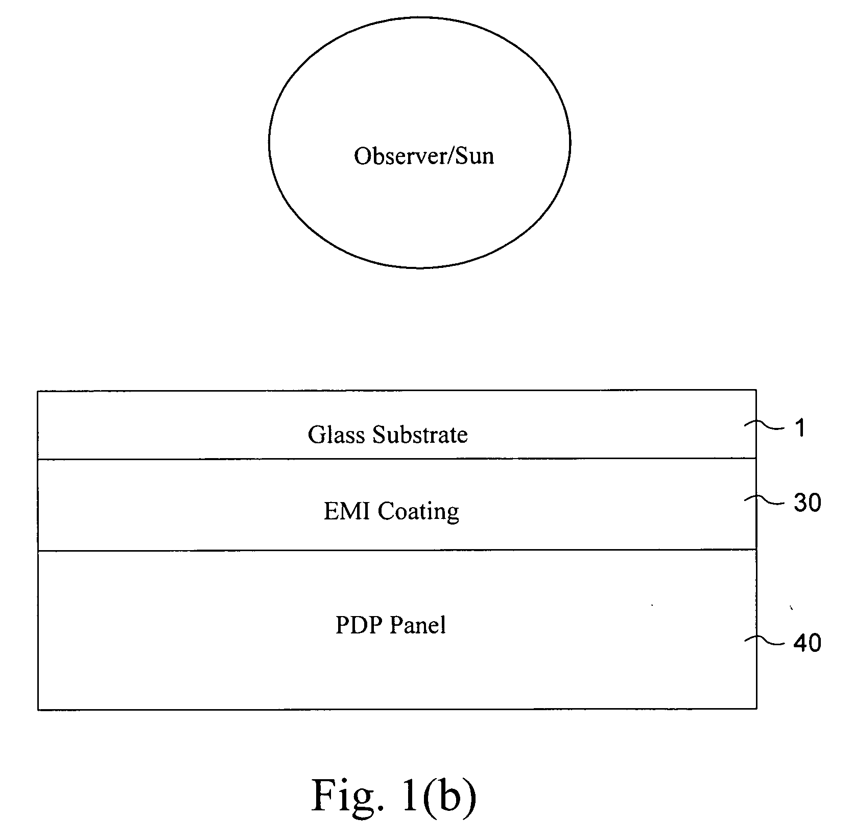
[0056]In certain example embodiments, a black frit and a silver frit comprise a filter frame and are supported by the filter such that the filter is closer to the glass substrate than either or both of the frits. Alternatively, in certain example embodiments, a conductive black frit comprises a filter frame and is supported by the filter such that the filter is closer to the glass substrate than the frit. Advantageously, a transparent conductive coating (TCC) may be coated on a stock, non-cut glass sheet, with the glass sheet later being cut to an appropriate size. In certain example embodiments, the TCC may be multi-layered and include 2 or more layers of silver.

[0057]For example, a TCC usable with certain example embodiments of this invention may be an Ag-based multiple layered TCC for display applications (e.g., PDP applicatio...


PUM

PropertyMeasurementUnit
refractive indexaaaaaaaaaa
thickaaaaaaaaaa
refractive indexaaaaaaaaaa

Abstract

A plasma display panel (PDP) includes a frameless EMI filter supported by a glass substrate for blocking / shielding substantial amounts of electromagnetic waves, with the filter being supported by a side of the substrate opposite a viewer. In certain example embodiments, the PDP filter includes a transparent conductive coating (TCC) for electromagnetic interference (EMI) and near infrared (NIR) blocking without the need for a conductive, peripheral buss bar. Additionally, in certain example embodiments, the need for a conductive frame is reduced or eliminated. The filter has high visible transmission, and is capable of blocking / shielding electromagnetic waves.

Description

CROSS-REFERENCE TO RELATED APPLICATIONS[0001]This application is a continuation-in-part of each of application Ser. No. 12 / 230,033 filed Aug. 21, 2008 and Ser. No. 12 / 230,034, filed Aug. 21, 2008, the entire contents of each of which are hereby incorporated herein by reference.FIELD OF THE INVENTION[0002]Certain example embodiments of this invention relate to a plasma display panel (PDP) including a filter supported by a glass substrate for blocking / shielding substantial amounts of electromagnetic waves, with the filter being supported by a side of the substrate opposite a viewer. More particularly, certain example embodiments relate to a PDP filter that includes a transparent conductive coating (TCC) for electromagnetic interference (EMI) and near infrared (NIR) blocking without the need for a conductive, peripheral buss bar. Additionally, in certain example embodiments, the need for a conductive frame is reduced or eliminated. The filter has high visible transmission, and is capab...

Claims


Application Information

Patent Timeline
Patent Type & Authority Applications(United States)
IPC IPC(8): H05K9/00H01J17/49
CPCH05K9/0096H05K9/0088C03C17/36C03C17/3626C03C17/3639C03C17/3644C03C17/3657C03C17/3676G02B1/11H05K9/00
Inventor DEN BOER, WILLEMLINGLE, PHILIP J.
Owner GUARDIAN GLASS LLC
Why Eureka
Try Eureka