Cathode for an electrochemical cell

a cathode and electrochemical technology, applied in the direction of non-aqueous electrolyte cells, cell components, conductors, etc., can solve the problems of reducing the capacity density of the resulting electrode, reducing the efficiency and increasing the rate of degradation of the performance of the electrochemical cell. , to achieve the effect of adversely increasing the hygroscopicity of the resulting cathod

Active Publication Date: 2010-03-18
GENERAL ELECTRIC CO
View PDF8 Cites 54 Cited by
  • Summary
  • Abstract
  • Description
  • Claims
  • Application Information

AI Technical Summary

Benefits of technology

[0042]An additional advantage of the invention is that hygroscopic components, the presence of which can adversely affect the formation of the first particulate material, can be included in the second particulate material. For example, of the total amount of sodium iodide in the particulate material, preferably from 50 to 100 wt %, such as from 60 to 99 wt % or from 70 to 99 wt %, most preferably from 80 wt % to 99 wt % (for example from 85 wt % to 95 wt %) is contained in the second particulate material with the remainder in the first particulate material. For example, the entirety of the sodium iodide in the cell may be present in the second particulate material.
[0043]A further advantage of the cathode of the present invention is that larger amounts (i.e., greater than 50%, preferably greater than 70%, 80% or 90%) of aluminium powder may be contained within the cathode, compared to granular cathodes that do not contain the second particulate material, without adversely increasing the hygroscopicity of the resulting cathode. This is because the majority or all of the aluminium powder may be present in the second particulate material, which may not be subjected to a granulation process.
[0044]In one embodiment, therefore, the second particulate material comprises a greater proportion by weight (i.e., greater than 50%, preferably greater than 70%, 80% or 90%) of a hygroscopic material such as aluminium or sodium iodide than the first particulate material. Preferably, the second particulate material comprises the entiret

Problems solved by technology

Although granular electrodes are easier to handle than powdered electrodes, it has now been found that when they are assembled into an electrochemical cell, gaps or spaces are created between the granules thereby reducing the capacity density of the resulting electrode.
This method also causes an undesirable increase in the utilisation of the metal because the increase in sodium chloride in the granules reduces the amount of metal in the electrode.
The higher the utilisation of the metal, the less metal available as a conducting backbone and the more rapid the rate of degradation of performance of the electrochemical cell.
H

Method used


Image

  • Cathode for an electrochemical cell
  • Cathode for an electrochemical cell
  • Cathode for an electrochemical cell

Examples


example 1

Construction of an Electrochemical Cell

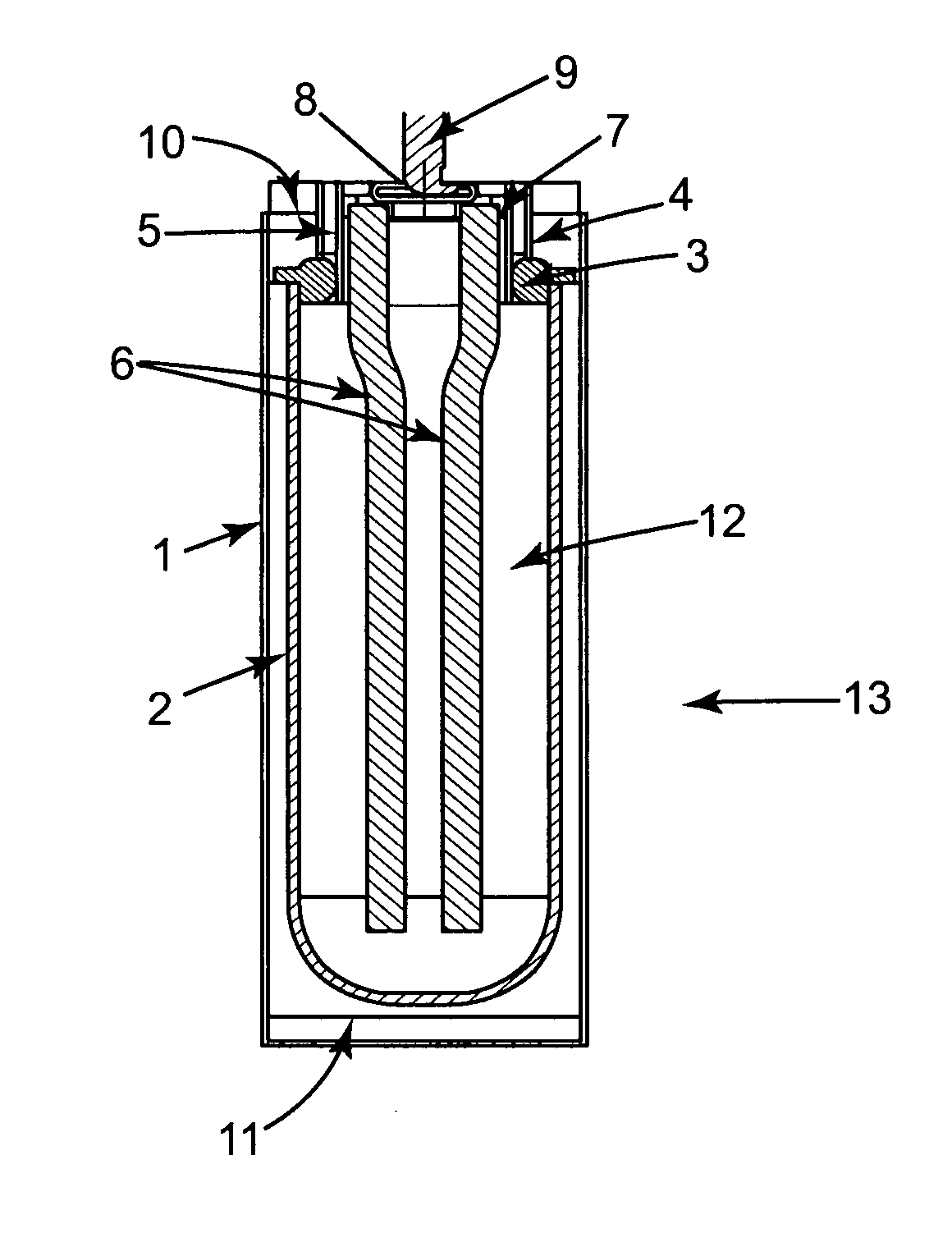
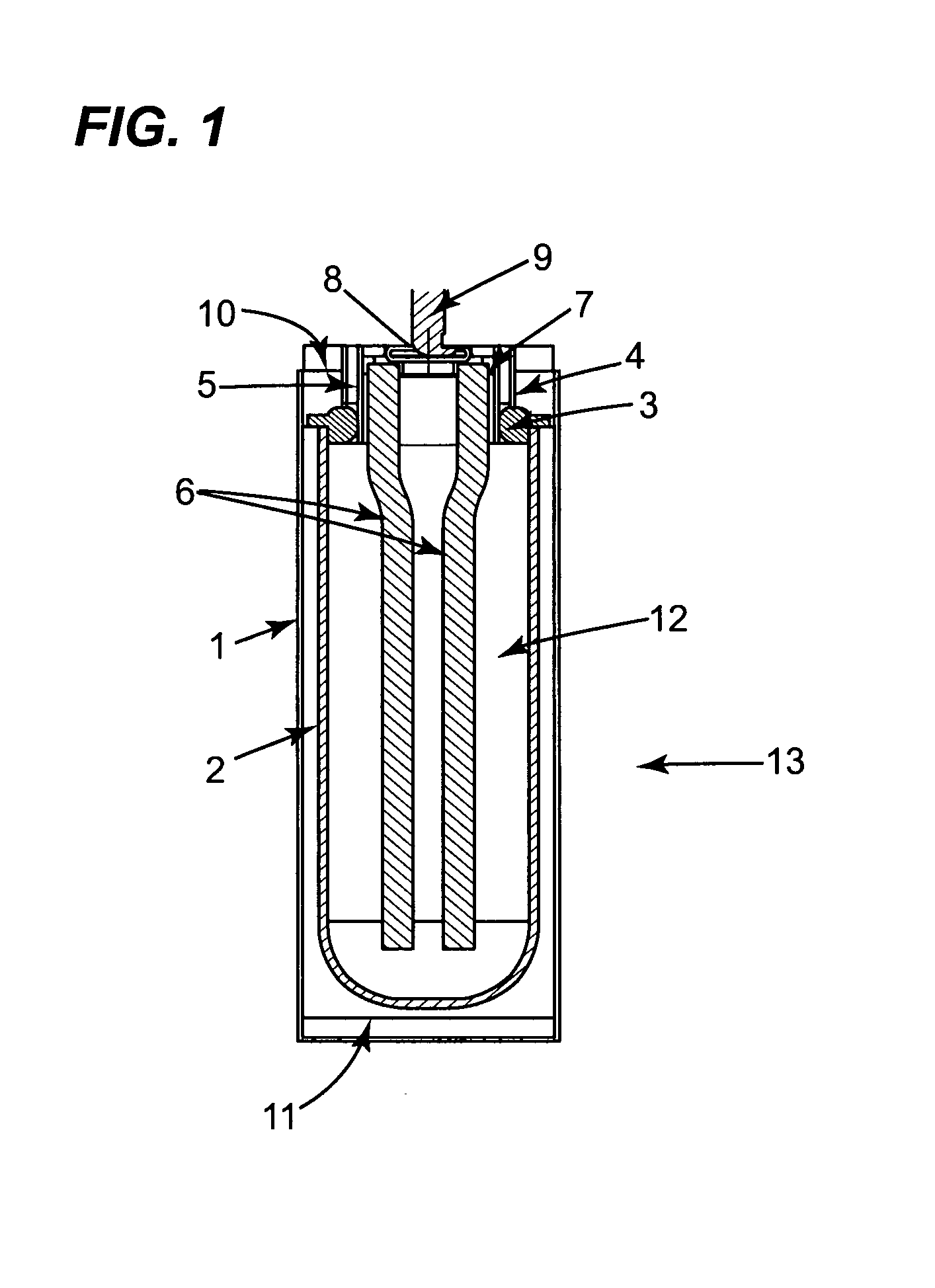
[0084]Referring to FIG. 1, the electrochemical cell 13 in accordance with the invention has a cylindrical casing 1. A beta alumina tube 2 is located concentrically within the casing. The tube 2 is attached to an alpha alumina ring 3, by means of a glass seal. Two nickel parts 4 and 5 are bonded to the alpha alumina ring 3 to provide a leak tight seal. A current collector assembly comprising two nickel wires 6 attached to a metal ring 7, is welded to the inner nickel ring 5. A closure cap 8 with positive terminal 9 is welded to the metal ring 7, closing off tube 2. A bridging piece 10 is welded to the outer nickel part 4 and the case 1 is welded to this bridging piece. A metal end cap 11 is welded to the case 1.

[0085]Around the outside of the tube 2 is a close fitting rolled steel shim (not shown) having at least two turns. This covers most of the tube 2 and extends to and is in electrical contact to the end cap 11. This configuration provides t...

example 2

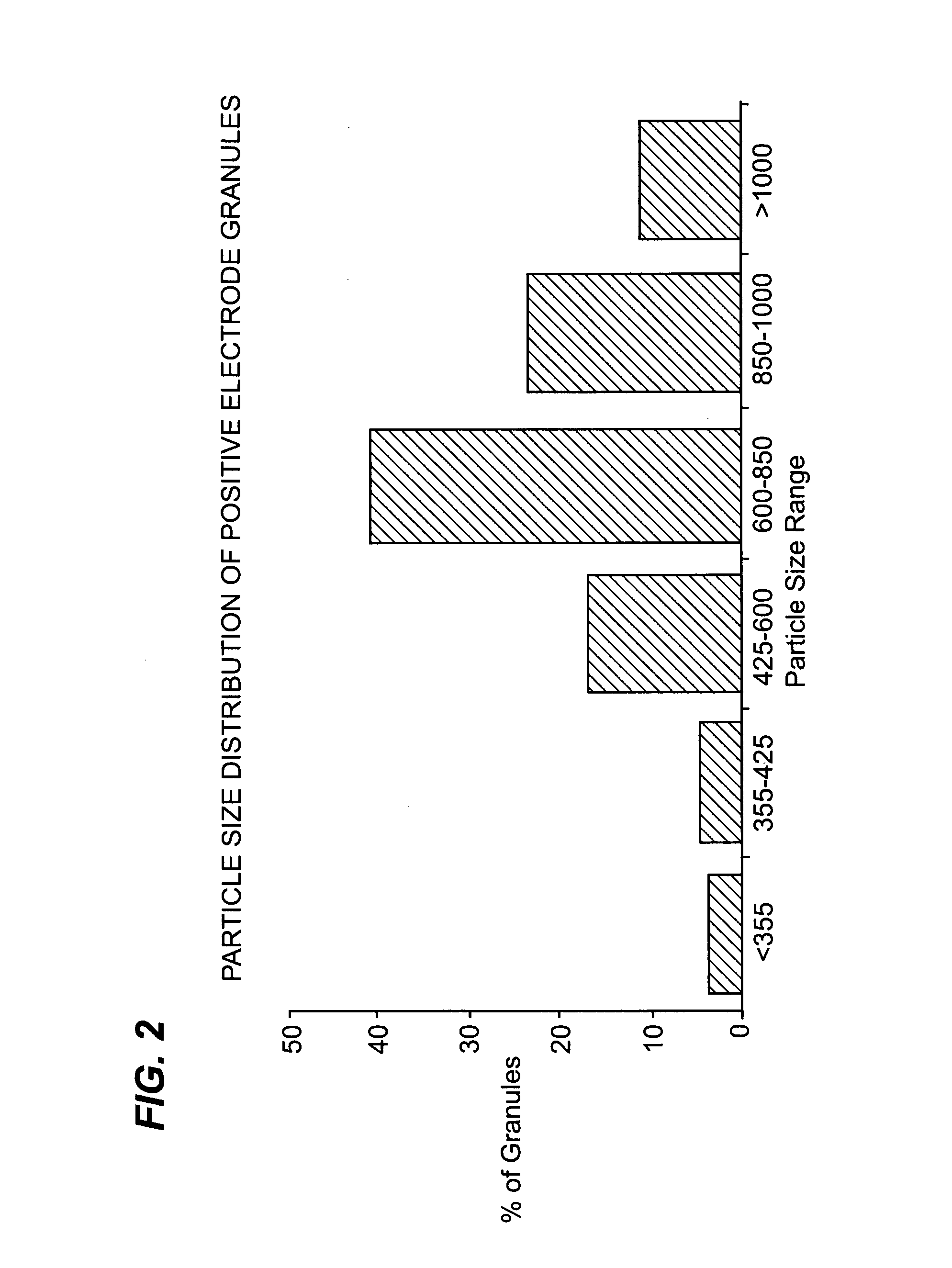
[0087]Positive electrode granules were manufactured using known methods by which a blended mixture of sodium chloride powder (a grade known as Microfine salt available from Custom Powders Ltd) having a particle size of less than 63 microns, nickel (INCO 287) powder, iron powder and small quantities of sodium fluoride, sodium iodide and aluminium powder, was dried and compacted into a dense sheet before being broken into granules with a size range as shown in FIG. 2. 80 g of these granules were vibrated into a beta-alumina tube of cell 13 in Example 1 (having an internal diameter of 28.5 mm and internal volume of 48 cc). The cell was heated to about 300° C. to remove any moisture. 37 g of molten sodium chloroaluminate was introduced under vacuum into the positive electrode compartment so that the molten salt dispersed about (impregnated) the granules. The positive electrode compartment was then sealed by welding on a top cap. The cell was then heated to 300° C. and charged at a curre...

example 3

[0089]Positive electrode granules were manufactured in accordance with the method of Example 2 above. 80 g of these granules were vibrated into a beta alumina tube of cell 13 in Example 1 (having an internal diameter of 28.5 mm and internal volume of 48 cc). Microfine salt was added to the granules whilst the beta alumina tube was being vibrated. The addition of Microfine salt was halted when it was visible on top of the granule bed. 10 g of Microfine salt was added. The cell was heated to above the melting point of the sodium chloroaluminate and 25.1 g of molten sodium chloroaluminate was introduced into the positive electrode compartment so that the molten salt dispersed about (impregnated) the granules and powder mix (Microfine salt). The positive electrode compartment was then sealed by welding on a top cap. The cell was heated to 300° C. and charged at a maximum current of 0.5 amps at a voltage of 2.67V. As in Example 2, the charge was terminated when the current fell to 0.2 am...


PUM


Abstract

The invention provides a cathode for an electrochemical cell comprising: a first particulate material having particles comprising a mixture of at least one alkali metal halide and at least one metal; and a second particulate material comprising at least one alkali metal halide, wherein the second particulate material has a particle size smaller than that of the first particulate material.

Description

BACKGROUND OF THE INVENTION[0001]The present invention relates to a cathode for an electrochemical cell. In particular, the cathode of the present invention is for use in a high temperature rechargeable electrochemical cell.[0002]It is known that an effective way of handling a cathode in the form of a powdered mixture (as described in GB 2,182,194 A, for example) is to form granules, as in GB 2,281,436 B. The resulting granules are free flowing and prevent segregation of the different constituents of the electrode. Typically, the granules contain nickel, iron, sodium chloride, sodium fluoride, sodium iodide and aluminium.[0003]Although granular electrodes are easier to handle than powdered electrodes, it has now been found that when they are assembled into an electrochemical cell, gaps or spaces are created between the granules thereby reducing the capacity density of the resulting electrode. While it has been found that it is possible to increase the capacity density by increasing ...

Claims


Application Information

Patent Timeline
IPC IPC(8): H01B1/22H01M4/06H01M4/02H01M4/58H01M10/0561H01M10/36
CPCH01M4/38H01M4/46H01M2004/028H01M10/0561H01M10/399H01M4/582Y02E60/10H01M4/48
Inventor SUDWORTH, JAMES
Owner GENERAL ELECTRIC CO
Why Eureka
Try Eureka