Tether-containing conducting polymers

a conducting polymer and tether technology, applied in the direction of liquid electrolytic capacitors, casings/cabinets/drawers, casings/cabinets/drawers details, etc., can solve the problems of limited ability to undergo repeated cycling of materials, high complexity of mass transport processes, and high cos

Active Publication Date: 2010-03-25
THE UNITED STATES OF AMERICA AS REPRESENTED BY THE SECRETARY OF THE NAVY
View PDF19 Cites 13 Cited by
  • Summary
  • Abstract
  • Description
  • Claims
  • Application Information

AI Technical Summary

Problems solved by technology

These mass transport processes are often highly complex, with the direction of motion dependent on ion charge, size, and solvation number.
It exhibited some diffusion gating effects that arose from the swelling and shrinking of the polymer that accompanies oxidation / reduction, although it was found that the material had a limited ability to undergo repeated be repeated cycling.
One drawback in state-of-the art electrochemical supercapacitors is that they require liquid electrolyte for the ion-pairing associated with charge storage.
The liquid contributes significantly to the weight of the device, and it tends to break down at higher voltages.

Method used


Image

  • Tether-containing conducting polymers
  • Tether-containing conducting polymers
  • Tether-containing conducting polymers

Examples


example 1

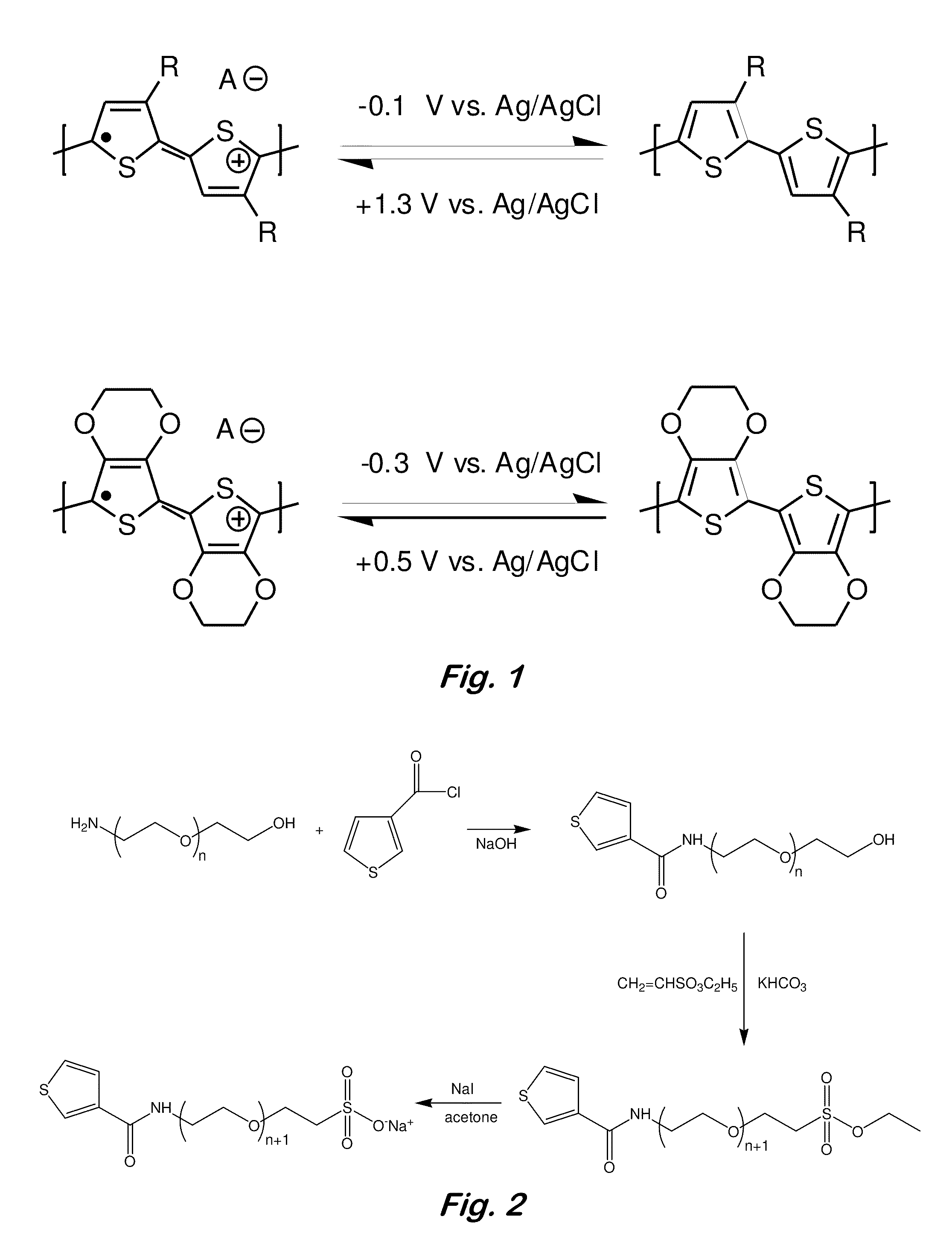
[0060]Chemical synthesis of TP—OEG-SO4 and DMTP—Solvents, gold wire, and precursors for the conducting polymers were purchased from Sigma-Aldrich. The monomer TP—OEG-SO4 was synthesized in four steps (FIG. 2). To form the tether precursor amide (Eq. (2)), a mixture (2.5 g, 19.5 mmol) of thiophene carboxylic acid, a molar excess of oxalyl chloride, and 1 drop of DMF in 10 mL of benzene was stirred overnight at room temperature (Marchand-Brynaert et al., Tetrahedron, 52 (1996) 5591). The solvent was removed under vacuum and the resulting residue was dissolved in THF. This solution was added dropwise at 0° C. to a stirred mixture of PEG-amine (Eq. (1)) (3.05 g, 16.0 mmol) in 50 mL of water and 1.28 g of NaOH. The reaction was stirred overnight at room temperature. The solution was acidified to a pH 4.0 with 1 N HCl solution. Extraction with ethyl acetate gave a yellow liquid. Gradient column chromatography in silica with ethyl acetate eluent followed by methanol yielded 2 g of the fina...

example 2

[0062]Electrochemical Synthesis of poly(TP—OEG-SO4) and poly(DMTP)—Dissolution of 15 mg TP—OEG-SO4 into 4:1 toluene:acetonitrile (v:v) containing 200 mM t-butylammonium hexafluorophosphate was followed by electropolymerization into a thin film onto a 0.2 mm diameter gold coil with a 1 cm2 immersion area using brief applications (90 seconds each) of 1.8 V vs. silver wire (power source CHI 660C Electrochemical Workstation, CH Instruments, Austin, Tex.). This particular solvent mixture was chosen because it supported the monomer as solute but the polymeric thin film had only a minimal solubility. A series of four applications of 1.8 V resulted in the deposition of 0.19 mg poly(TP—OEG-SO4) onto the gold coil, determined gravimetrically and by coulometry. In a similar manner, DMTP was electropolymerized onto a gold coil, forming a thin film of mass 0.30 mg. Cyclic voltammetry studies were performed at 18° C. in a sealed cell using a CHI 660C Workstation, in the solvent system 4:1 toluene...

example 3

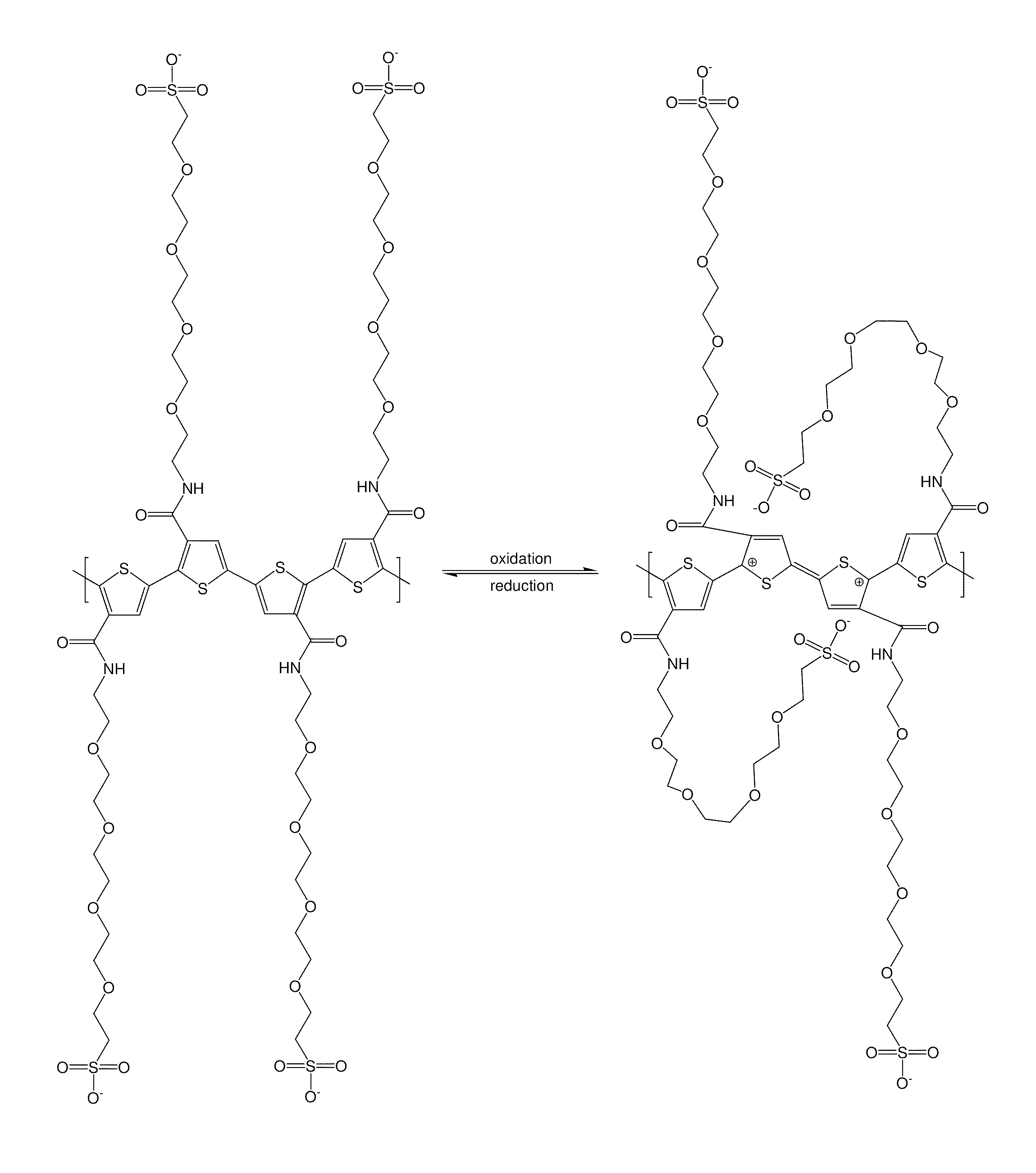
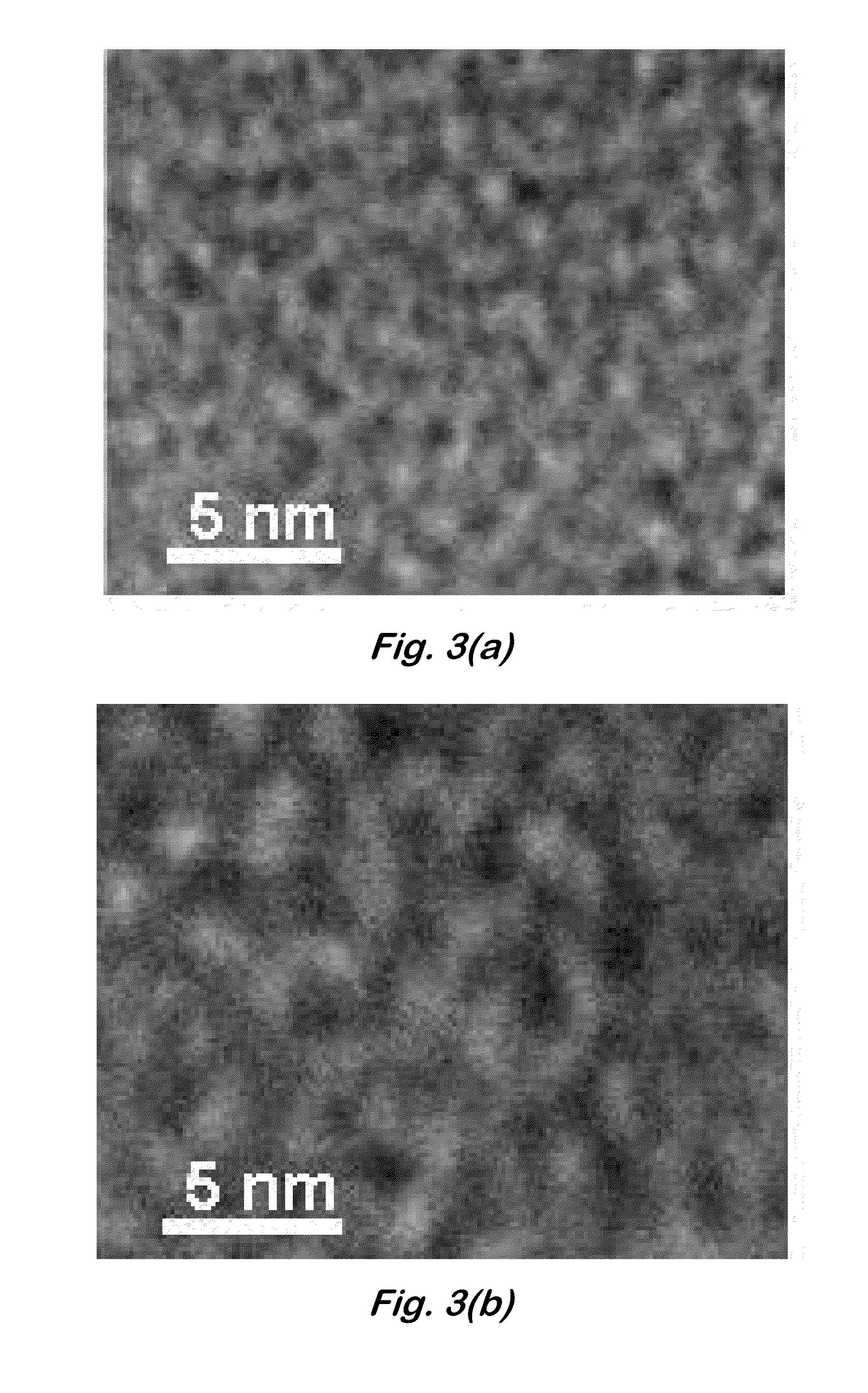
[0063]TEM of polymers—Monomer was electropolymerized onto copper TEM grids in a manner similar to that described above. The grids were washed to remove dried salts, and viewed with a transmission electron microscope (Libra 120, Carl Zeiss SMT, Peabody, Mass.) at 120 kV. Images were captured on a bottom-mounted digital camera (Olympus SIS, Montvale, N.J.). FIG. 3 shows TEMs of the closed (a) and open (b) states. They clearly indicate that the polymer fine structure changes with oxidation state, with porous regions (lighter areas) becoming significantly larger when the polymer is switched into its oxidized form. If the sulfonate tethers form intra-molecular ion pairs, they would vacate the regions farther away from the polymer main chains and cause the electron density there to drop. Simultaneously, the darker regions (which correspond to polymer-rich regions), would become enlarged. This is, in fact, what is seen in the image. The polymer may assemble into larger aggregates when oxid...


PUM

PropertyMeasurementUnit
specific capacitancesaaaaaaaaaa
operational voltageaaaaaaaaaa

Abstract

A compound having the formula below. X is hydroxyl, a sulfonic ester or salt thereof, a phosphonate or salt thereof, a carboxylate or salt thereof, or a boronic ester or salt thereof. The value n is an integer greater than or equal to 2. A polymer made by polymerizing the compound. A method of: reacting NH2—(CH2—CH2—O)n—CH2—CH2—OH with thiophene acid chloride to form a (SC4H3)—CO—NH—(CH2—CH2—O)n—CH2—CH2—OH amide; reacting the amide with a vinyl sulfonic ester, a vinyl phosphonate, a vinyl carboxylate, or a vinyl boronic ester to form an intermediate; and converting the intermediate to a salt form.

Description

[0001]This application claims the benefit of U.S. Provisional Application No. 61 / 098,905, filed on Sep. 22, 2008. The provisional application and all other publications and patent documents referred to throughout this nonprovisional application are incorporated herein by reference.TECHNICAL FIELD[0002]The present disclosure is generally related to conductive polymers.DESCRIPTION OF RELATED ART[0003]Extended π-conjugated electrically conducting oligomers and polymers have unique properties that have impacted diverse technologies, and have resulted in the appearance of new ones (Shirakawa et al., Makromolec. Chemie, 179, 6, (1978) 1565; Chiang et al., J. Am. Chem. Soc. (1978) 100, 1013). A partial list of applications includes micro- and nanoscale circuitry, throwaway electronic devices such as plastic electrochromic displays, flexible displays, lightweight storage batteries, corrosion protection coatings, antistatic coatings, bio- and chemical sensors, and military applications such ...

Claims


Application Information

Patent Timeline
Patent Type & Authority Applications(United States)
IPC IPC(8): H01G9/00C07D333/04C08G75/06H01G9/016
CPCC07D333/38C08G61/126C08G65/3324C08G65/3344C08G65/3346C08G2261/1424Y10T29/417C08G2261/1452C08G2261/44C08G2650/50H01G9/028Y10T29/41C08G2261/1432
Inventor MARTIN, BRETT D.RATNA, BANAHALLI R.NACIRI, JAWADMARKOWITZ, MICHAEL A.
Owner THE UNITED STATES OF AMERICA AS REPRESENTED BY THE SECRETARY OF THE NAVY
Why Eureka
Try Eureka