Fiber structure and method for production thereof

Inactive Publication Date: 2010-03-25
TORAY IND INC
View PDF3 Cites 22 Cited by
  • Summary
  • Abstract
  • Description
  • Claims
  • Application Information

AI Technical Summary

Benefits of technology

[0025]According to embodiments of the present invention, it is possible to easily obtain a fiber structure in which ultrafine fibers are dispersed on a single fiber. When such a fiber structure is used as a polishing cloth, a polishing load is dispersed in the ultrafine fibers dispersed in a monofilamentous state, and thus uniform polishing with high smoothness can be conducted. Further, since moderate void spaces exist between the ultrafine fibers, the fiber structure has a high ability of holding abrasive grains. When the fiber structure is used as a polishing cloth, agglomeration of abrasive grains is suppressed and scratches are less likely to be made. When the fiber structure is used as a wiper, the fiber structure has a high ability of trapping stains.
[0026]The fiber structure of an embodiment of the present invention has a lot of very small void spaces between fibers compared to a conventional fibe

Problems solved by technology

Further, in the case of wiping in everyday life, foreign matters are put between a wiping cloth and an object during wiping and larger scratch is likely to be made.
Therefore, a range of application of the conventional wiping clothes is limited to glasses, liquid crystal displays of domestic digital video cameras, and the like, and there has been a problem that the conventional wiping clothes cannot be applied to objects which are soft and easily scratched, for example, contact lens, silver products, and the like.
Furthermore, the conventional wiping clothes have had not satisfactory wiping properties for stains in fine unevennesses of the object.
It is considered that, since the conventional microfibers have a single fiber diameter of about 2 to 5 μm and, when pressed against the object, stress concentration is likely to occur on the surface of the object, scratches are likely to be made.
It is also considered that, when foreign matters are put between a wiping cloth and an object, since the foreign matters are pressed against them, and then are in a state of being polished by the foreign matters, scratches are likely to occur.
It is also presumed that, when stains penetrate into micro-level unevennesses of an object, ev

Method used


Image

  • Fiber structure and method for production thereof
  • Fiber structure and method for production thereof
  • Fiber structure and method for production thereof

Examples


example 1

Production of Nonwoven Fabric

[0125]Nylon 6 (hereinafter referred to as N6) having melt viscosity of 212 Pa·s (262° C., shear rate: 121.6 sec−1) and a melting point of 220° C. and poly-L-lactic acid (optical purity: 99.5% or more) having a weight average molecular weight of 120,000, melt viscosity of 30 Pa·s (240° C., 2432 sec−1) and a melting point of 170° C. were used and the content of N6 was adjusted to 45% by weight, and then the mixture was melt-kneaded at a kneading temperature of 220° C. to obtain polymer alloy tips.

[0126]The weight average molecular weight of poly-L-lactic acid was determined by the following procedure. A chloroform solution of a sample was mixed with THF (tetrahydrofuran) to obtain a measuring solution. The concentration of polylactic acid was adjusted to 0.4% by weight. Using gel permeation chromatography (GPC) Waters 2690 manufactured by Waters Corporation, a polystyrene equivalent weight average molecular weight was determined by measuring at 25° C. The ...

example 2

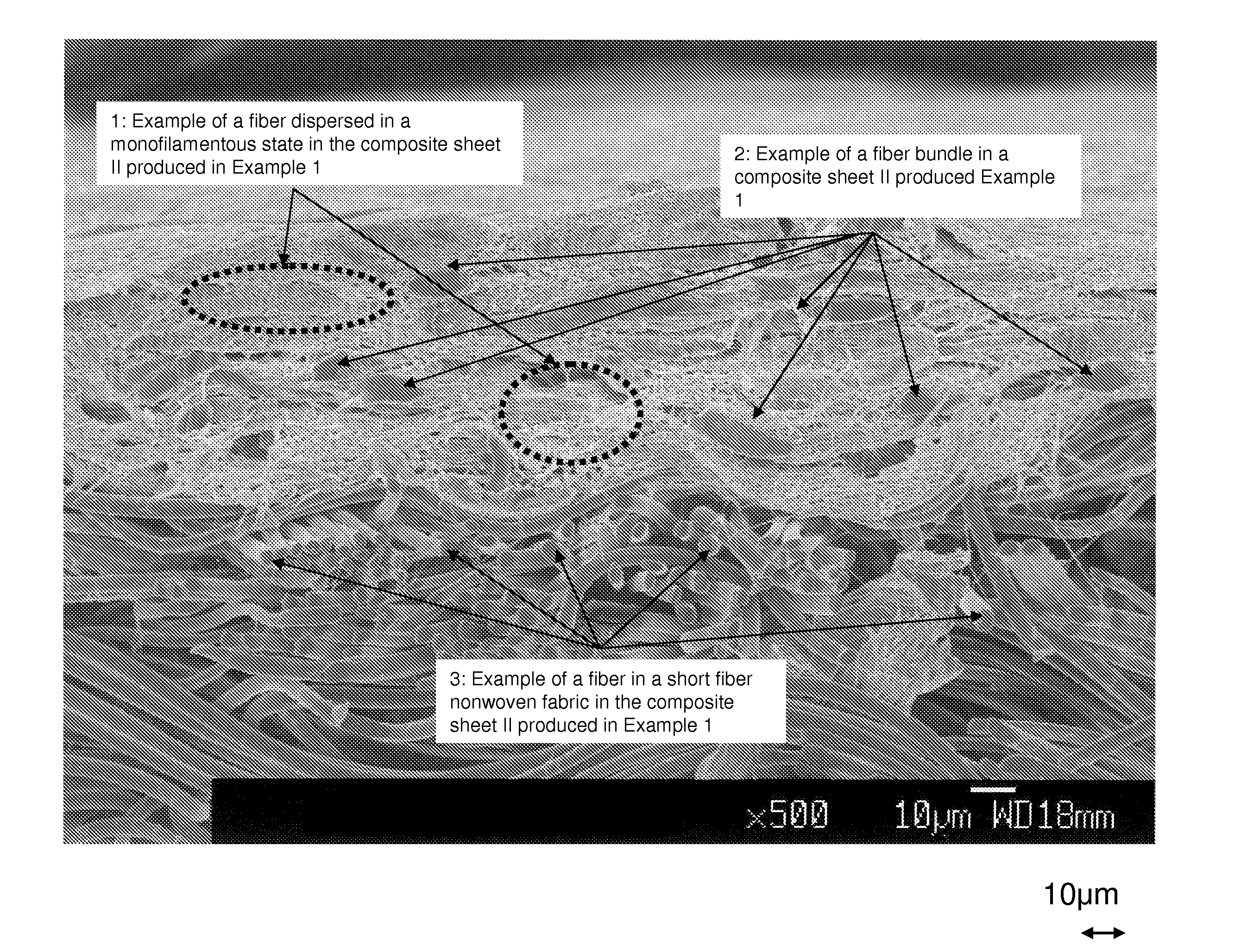
[0133]Two kinds of nonwoven fabrics were integrated by conducting a treatment of injecting a water flow to the composite sheet I obtained in Example 1 under the same conditions as in Example 1, except that the pressure of the water flow was adjusted to 1 MPa. The thus obtained sheet is referred to as a composite sheet III. The composite sheet III was observed by SEM. As a result, the entire surface of the fiber structure is covered with fibers (B) having a number average fiber diameter of 110 nm in a monofilamentous state without clearance. In the cross-section, the fibers (B) having a fiber diameter of 1 μm or less (number average fiber diameter: 110 nm) dispersed in a monofilamentous state form fine void spaces due to tangles or bends and also exist together with a fiber bundle (A) having a fiber bundle diameter 15.5 μm).

[0134]The obtained composite sheet was slitted to give a tape having a width of 38 mm and polishing characteristics were evaluated. The composite sheet had a thic...

example 3

[0136]The fiber structure obtained in Example 1 was embossed to form random strip-shaped concave portions. The treating rate was 1.5 m / min and the temperature of a sculpted roll was 140° C. On the surface after embossing, stripe-shaped recesses having a depth of several micron meter which surround a region of about 500 μm were formed. Under the same conditions as in Example 1, the disk was polished. As a result, the disk after polishing showed surface roughness of 0.27 nm and the number of scratches of 1.2 and is extremely excellent in smoothness and low scratch properties. The polishing rate was high such as 4.6 mg / min.


PUM

PropertyMeasurementUnit
Temperatureaaaaaaaaaa
Lengthaaaaaaaaaa
Lengthaaaaaaaaaa

Abstract

A fiber structure including: (A) a single fiber having a fiber diameter of 3 μm or more and/or a fiber bundle having a fiber bundle diameter of 3 μm or more, and (B) a single fiber having a fiber diameter of 1 μm or less, wherein the component (A) has a number average fiber diameter and/or a number average fiber bundle diameter of 4 μm or more, at least a part of the component (B) is dispersed in the component (A) in a monofilamentous state in the cross-section taken in the thickness-wise direction of the fiber structure, at least a part of the component (B) dispersed in the monofilamentous state is bent and/or tangled to form a void space, and at least one surface of the fiber structure is covered with the component (B).

Description

FIELD OF THE INVENTION[0001]The present invention relates to a fiber structure in which fibers are dispersed in a monofilamentous state, and a method for production thereof.BACKGROUND OF THE INVENTION[0002]Heretofore, so-called microfibers having a single fiber diameter of 2 to 5 μm have been suitably used for eyeglass wipers, display wiping clothes for lens and electronic equipment, and the like. Recently, wiping clothes made of combined filament yarns of microfibers and high shrinkage yarns have been proposed to improve wiping properties and dimensional stability by the densification of fabrics (Patent Document 1).[0003]However, the conventional wiping clothes sometimes scratch an object itself by a wiping operation depending on the object. Further, in the case of wiping in everyday life, foreign matters are put between a wiping cloth and an object during wiping and larger scratch is likely to be made. Therefore, a range of application of the conventional wiping clothes is limited...

Claims


Application Information

Patent Timeline
IPC IPC(8): D02G3/22B29C47/00D04H1/435D04H1/46D04H1/498D04H3/011D04H3/016D04H3/018D04H5/03
CPCD03D1/0023Y10T428/2922D03D15/0061D04H1/435D04H1/46D04H1/498D04H3/011D04H3/016D04H3/018D04H5/03D04H13/002D04H13/005D03D15/0027D03D15/0083D03D15/0094D03D27/10D10B2321/02D10B2331/02D10B2331/04D10B2401/024D10B2401/041D03D15/00D03D15/33D03D15/43D03D15/292D03D15/283
Inventor HASHIMOTO, TAKAFUMINONAKA, SHUICHIIIJIMA, HIROMICHIMURAKAMI, KAKUJI
Owner TORAY IND INC
Why Eureka
Try Eureka