Electrode catalyst for a fuel cell, and fuel cell using the same

Inactive Publication Date: 2010-04-15
NAT INST OF ADVANCED IND SCI & TECH
View PDF1 Cites 25 Cited by
  • Summary
  • Abstract
  • Description
  • Claims
  • Application Information

AI Technical Summary

Benefits of technology

[0026](1) The electrode catalyst of the present invention for fuel cells is specified by the use of, as a support, a mesoporous carbon support which is obtained by drying, baking, and carbonizing a mixture of a surfactant and carbon precursors. A mesoporous carbon material obtained in the above, can be synthesized by such a simple step that the surfactant and the carbon precursors are baked and carbonized, by utilizing self-organization of those, thereby to conduct finally the carbonization and the removal of the surfactant at the same time.
[0027](2) The mesoporous carbon particles obtained by the synthetic method as in the above, have the physical properties of: a specific surface area of 500 to 700 cm2/g; a regular mesoporous structure; and an average diameter of 5 to 10 nm.
[0028](3) A conventional mesoporous carbon material that has been used as this type of catalyst support, needs to adopt the following complicated steps of: making to adsorb and impregnated porous particles, such as silica (silica template) and titania, having an intended pore distribution (mesoporous), with a carbon-containing molecule, such as sucrose; carbonizing the carbon-containing molecule in an inert atmosphere; and then dissolving/removing the template particles, such as silica, by hydrofluoric acid, NaOH/EtOH, or the like. However, the mesoporous carbon material according to the present invention, has the advantage that a highly active catalyst support can be obtained by a simple process, without adopting su

Problems solved by technology

However, when a conventional carbon black support is used, there arises the problem that catalyst particles carried in micropores cannot be brought into contact with ionomers and do not contribute to the reaction, resulting in a low catalyst utilization (efficiency).
Thus, if the catalyst is mixed with the ionomers required during the course of assembly of an actual fuel cell, there arises the problem that the catalyst particles slip out of the carbon black support, and it is also pointed out that

Method used


Image

  • Electrode catalyst for a fuel cell, and fuel cell using the same
  • Electrode catalyst for a fuel cell, and fuel cell using the same
  • Electrode catalyst for a fuel cell, and fuel cell using the same

Examples


example 1

Synthetic Example 1 of a Mesoporous Carbon Material

Acidic Condition

[0098]Resorcinol (manufactured by Wako Pure Chemical Industries Ltd.) in an amount of 1.65 g was dissolved in 4.35 g of deionized water / 5.75 g of ethanol (manufactured by Wako Pure Chemical Industries Ltd.) / 0.15 mL of 5M hydrochloric acid (manufactured by Wako Pure Chemical Industries Ltd.). To the resultant solution, 0.945 g of Pluronic F-127 (manufactured by SIGMA) was added, to dissolve the resultant mixture completely. Then, 1.2 g of triethyl orthoacetate (manufactured by Wako Pure Chemical Industries Ltd.) and 1.35 g of 37% formaldehyde manufactured by Wako Pure Chemical Industries Ltd.) were added thereto, and the resultant mixture was stirred at 30° C. for 20 minutes. This solution was poured into a Teflon (registered trademark) container, which was then heated at 105° C. for 6 hours in an air blowing thermohygrostat (DMK300, manufactured by Yamato Scientific Co., Ltd.), to polymerize resorcinol and formaldehy...

synthetic example 2

of a Mesoporous Carbon Material

Alkaline Condition

[0103]The reaction was run in the same manner as in Synthetic Example 1, except that 1.0 mL of 0.5M NaOH (manufactured by Wako Pure Chemical Industries Ltd.) was used in place of hydrochloric acid in Synthetic Example 1. As a result, 0.8 g of a mesoporous carbon material was obtained as a black powder.

(Specific Surface Area of the Mesoporous Carbon Material Obtained in Synthetic Example 1 and Average Diameter of Mesopores)

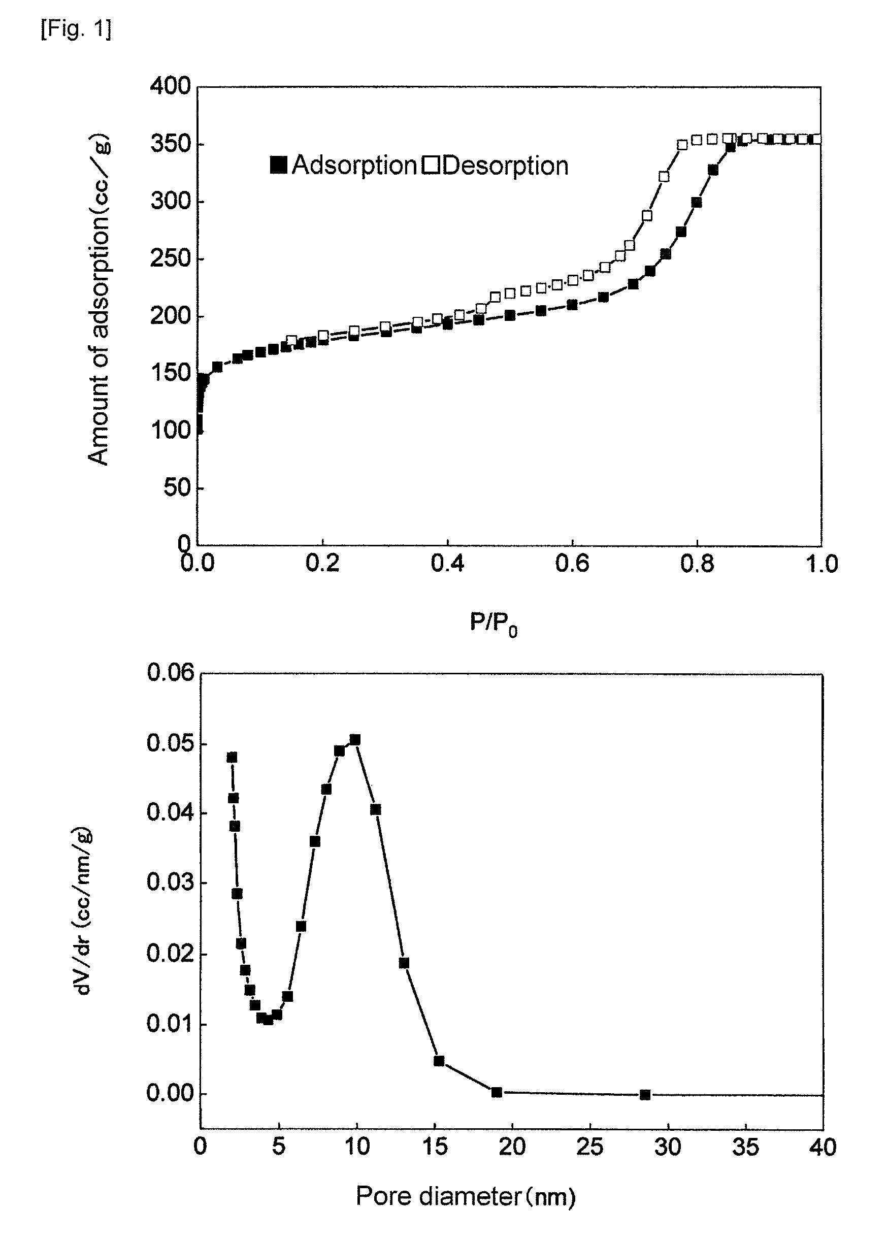
[0104]The measurement of adsorption of nitrogen to the product obtained in Synthetic Example 1 was made, using an independent multi-port-type specific surface area / pore distribution measuring device (QUADRASORB SI, manufactured by Qantachrome).

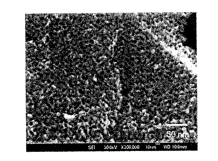
[0105]The mesoporous carbon material in an amount of 0.067 g, which was dried at 200° C. for 2 hours as a pretreatment, was utilized in measurement. As a result, it was found that the specific surface area was 600 cm2 / g and the average pore diameter was 7 to 8 nm. (FIG. 1)

(SEM ...

example 2

Production of a Mesoporous Carbon Membrane

[0129]Resorcinol (manufactured by Wako Pure Chemical Industries Ltd.) in an amount of 0.41 g was dissolved in 1.09 g of deionized water / 1.44 g of ethanol (manufactured by Wako Pure Chemical Industries Ltd.) / 0.375 mL of 5M hydrochloric acid (manufactured by Wako Pure Chemical Industries Ltd.). To the resultant solution, 0.236 g of Pluronic F-127 (manufactured by SIGMA) was added, to dissolve the resultant mixture completely. Then, 0.30 g of triethyl orthoacetate (manufactured by Wako Pure Chemical Industries Ltd.) and 0.34 g of 37% formaldehyde manufactured by Wako Pure Chemical Industries Ltd.) were added thereto, and the resultant mixture was stirred at 30° C. for 20 minutes. Then, 3 μL of this solution was cast, on a carbon rod (manufactured by Tokai Carbon), which was then heated at 95° C. for 6 hours in an air blowing thermohygrostat (DMK300, manufactured by Yamato Scientific Co., Ltd.), to polymerize resorcinol and formaldehyde.

[0130]Th...


PUM


Abstract

To provide an electrode catalyst for fuel cells, which is obtained efficiently by a simple process, without using a silica template, unlike in the conventional process, which is relatively large in mesopore diameter (5 nm or more), which enables catalyst particles deposited stably in the mesopores, and which can readily develop a highly triple-phase interface state.
Such an electrode catalyst for a fuel cell is constituted with: a mesoporous carbon support obtained by heating and baking for carbonization a mixture of a surfactant and carbon precursors; and catalyst particles carried by the support. Further, it is possible to obtain a fuel cell, which has: a fuel electrode; an air electrode; and an electrolyte membrane interposed between the electrodes, in which at least one of the fuel electrode and the air electrode contains the electrode catalyst.

Description

TECHNICAL FIELD[0001]The present invention relates to an electrode catalyst for a fuel cell, and to a fuel cell using the same.BACKGROUND ART[0002]Fuel cells, especially polymer electrolyte fuel cells (PEFCs), have recently attracted remarkable attention as energy sources of transportation means, from the viewpoint that they work at low temperatures and can be formed in small-sizes.[0003]PEFCs generally have a structure in which a fuel electrode (anode) and an air electrode (cathode) are disposed so as to sandwich a solid polymer electrolyte membrane between those, and in which a fuel, such as hydrogen, natural gas, or methanol, is supplied to the anode and an oxidizing agent, such as oxygen, or the air, is supplied to the cathode. Hydrogen ions and electrons are generated by an oxidation reaction on the anode. The hydrogen ions are transferred to the cathode by the solid polymer electrolyte membrane, and the transferred hydrogen ions are allowed to react with the oxidizing agent su...

Claims


Application Information

Patent Timeline
IPC IPC(8): H01M4/96B01J21/18
CPCH01M4/90H01M4/9083Y02E60/50H01M4/926H01M2008/1095H01M4/92
Inventor HAYASHI, AKARIYAGI, ICHIZOUKIMIJIMA, KENICHI
Owner NAT INST OF ADVANCED IND SCI & TECH
Why Eureka
Try Eureka