Furthermore, surgeries are an immense cost for the patient as well as for health insurance.
The main problem with attempts to replace damaged tissue in
living systems is the natural reaction of the body to destroy any
foreign object or—if that is not possible—to encapsulate it in fibrous tissues and separate it from its environment.
This makes the fixation of the
implant very difficult.
This is the loss of bone that occurs when stress is diverted from the area adjacent to the implant, due to the large difference in stiffness.
These factors have lead to technical and material challenges in long term fixation of orthopaedic bone implants and joint replacements.
It also lacks
adhesive properties, and therefore acts simply to fill the gaps between the implant and the bone to help the bone support the implant.
Motion and
rubbing within the joint can result in breakdown of the
cement, leading to the implant becoming loose, further pain and the loss of function of the implant.
PMNA is adequate for approximately 10 years, but failures are frequent after 15 years.
This technique is therefore inadequate for younger patients since revision of the
bone cement is difficult.
This method overcomes the problems associated with using
bone cement; however it also introduces new problems.
The revision of implants using biological fixation is very difficult due to the implant being directly connected to the bone.
Higher Ca / P ratio leads to the formation of CaO, which is reported to decrease strength and can furthermore lead to decohesion due to stresses from the formation of Ca(OH)2 and CaCO and related volume changes [Suchanek, Yoshimura, 1998].
Unfortunately, the fatigue properties of pure HA are very, poor compared to bone.
Additionally, the Weibull-modulus of HA in wet environments is low (m=5-12) which indicates low reliability of HA implants [Suchanek, Yoshimura, 1998].
Therefore it is not possible to
expose HA-implants to high dynamic loadings as experienced in human joints.
A big problem is the mismatch of the
thermal expansion coefficient of HA (15 10−6 / ° C.) and
titanium alloys (8.8 10−6 / ° C.).
Common
coating processes require high temperatures,
cooling down leads to different shrinkage behaviour that causes precracks at the interface [Breme et al, 1995].
Attempts to use processes at lower temperatures have not been commercially accepted up to now.
The particles experience a rapid
cooling rate of approximately 105 K / s [Park et al, 1999] when hitting the surface of the substrate and this leads to various disadvantageous effects:1. Although HA and Ti are exposed to high temperatures the rapid
cooling rate of the HA particles hinders chemical reactions and therefore strong chemical bonds between the HA and the
titanium [Park et al, 1999]; [Tsui et al, 1998a]; [Tsui et al, 1998b]; this results in poor adhesion of the HA onto the Ti or other
metal.2. The formation of metastable and amorphous CaP phases is undesirable for three reasons.
Secondly, although the
bone growth occurs at a faster rate in the presence of an
amorphous phase because of the
initiation of a fast
dissolution [Sun et al, 2001], the readily resorbtion by body fluids leads to a serious weakening of the interface between
coating and implant [Park et al, 1999]; [Dong et al, 2003]; [Cheang et al, 1996] as well as the production of particle debris in long term [Sun et al, 2001].
The higher
porosity also makes the HA susceptible to corrosive attacks, since the
coating is not dense enough to protect the underlying
titanium [Knets et al, 1998].
This technique has been faced with challenges of producing a controllable
resorption response in clinical situations.
The inherent
physics of
plasma spraying methods as well as other so called “wet” methods lead to the resulting deposits being thick, non adherent and structurally fragile.
These factors lead to deposits which can easily and readily crumble, flake or fall off the implant prior to and during implementation.
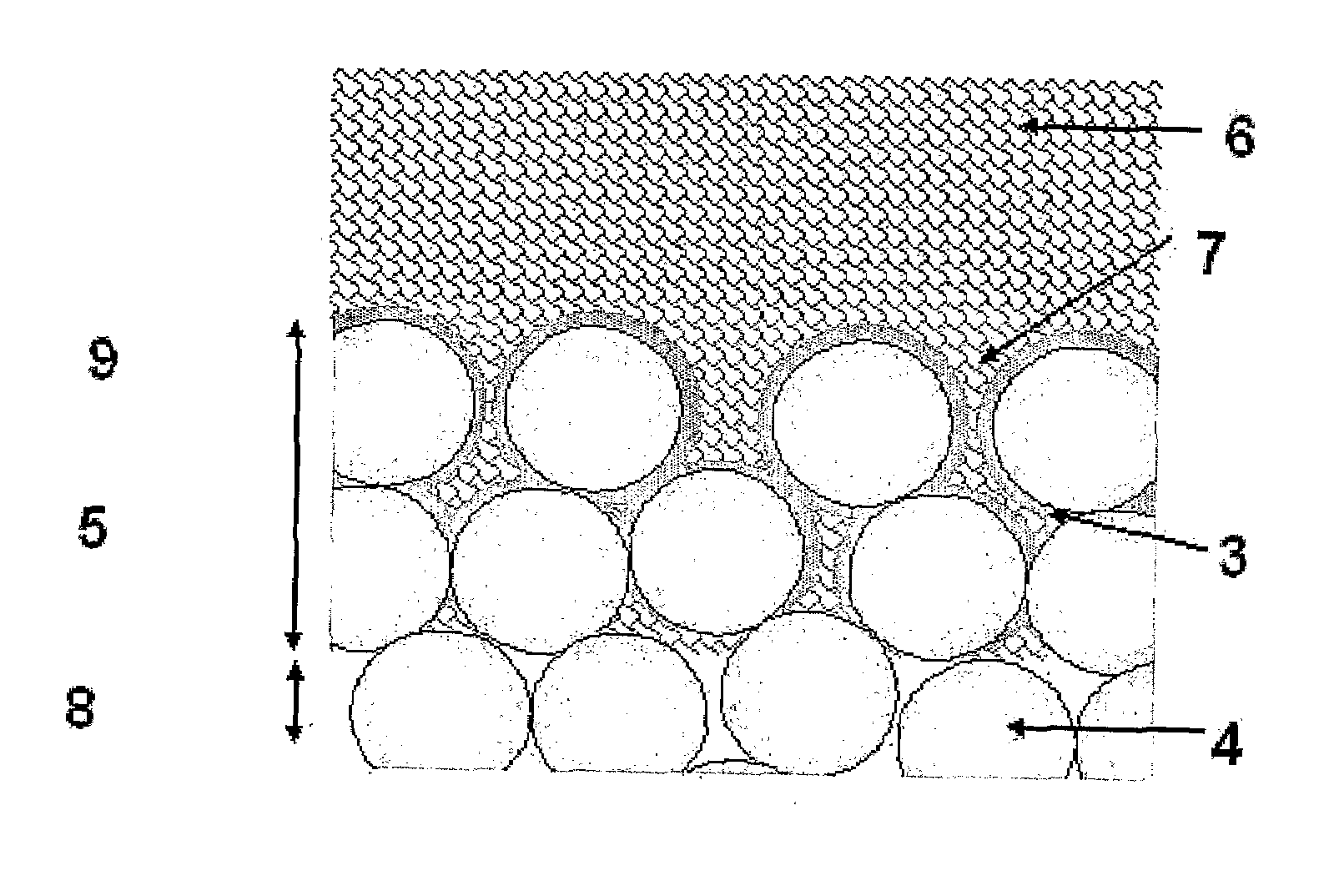
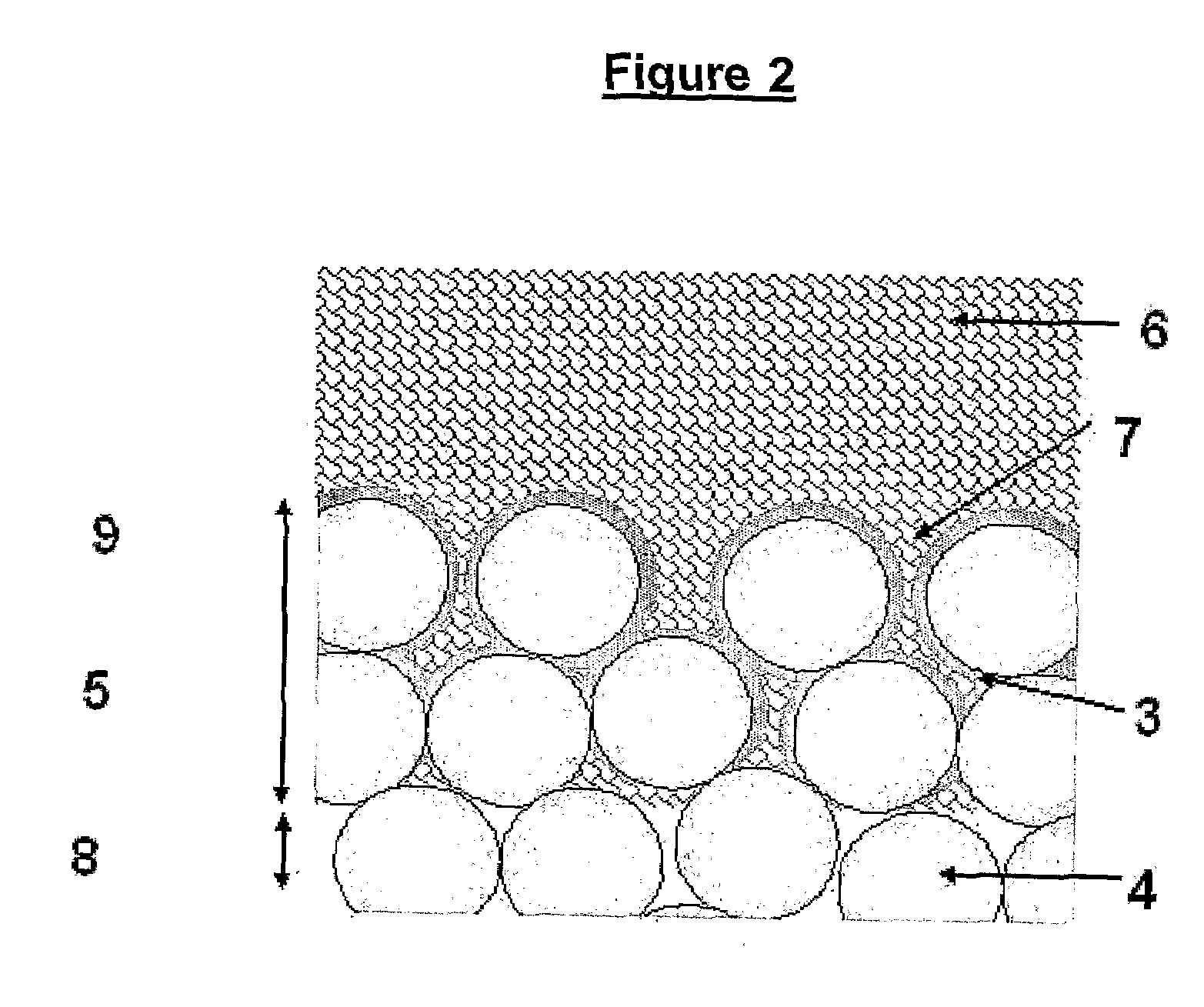
“Wet”
processing methods also lead to thick deposits which can block the pores of the porous material and therefore decrease the efficiency of the biological fixation.
“Wet”
processing methods do not penetrate the porous surface matrix and therefore do not lead to good adhesion of either the HA or bone to the
metal.
These are all significant disadvantages, and prevent the formation of a thin, consistent and reliable coating which allows for bone in growth and therefore biological fixation.
Issues of adhesion to the
metal structure and strength of the resulting bone have not been resolved for these methods.
Current
sol-gel and
plasma spray methods would not be capable of deposition of HA into porous structures and would block up the holes or pores and therefore prevent the desired in-growth.
The precursors used in those studies were introduced into the
reaction chamber by sublimation, which places considerable limitations on the choice of precursor (as they must be sufficiently volatile) and the ability to accurately measure the quantities of precursors that are being introduced under given sets of conditions.

