
Optical measuring instrument

a measuring instrument and optical technology, applied in the field of optical measuring instruments, can solve the problems of lack of automated documentation, lack of important features, limitations of lateral flow immunoassays, etc., and achieve the effects of high accuracy and sensitivity, convenient operation and operation robustness, and low weigh

Inactive Publication Date: 2010-05-06
QIAGEN LAKE CONSTANCE GMBH
View PDF5 Cites 24 Cited by
  • Summary
  • Abstract
  • Description
  • Claims
  • Application Information

AI Technical Summary

Benefits of technology

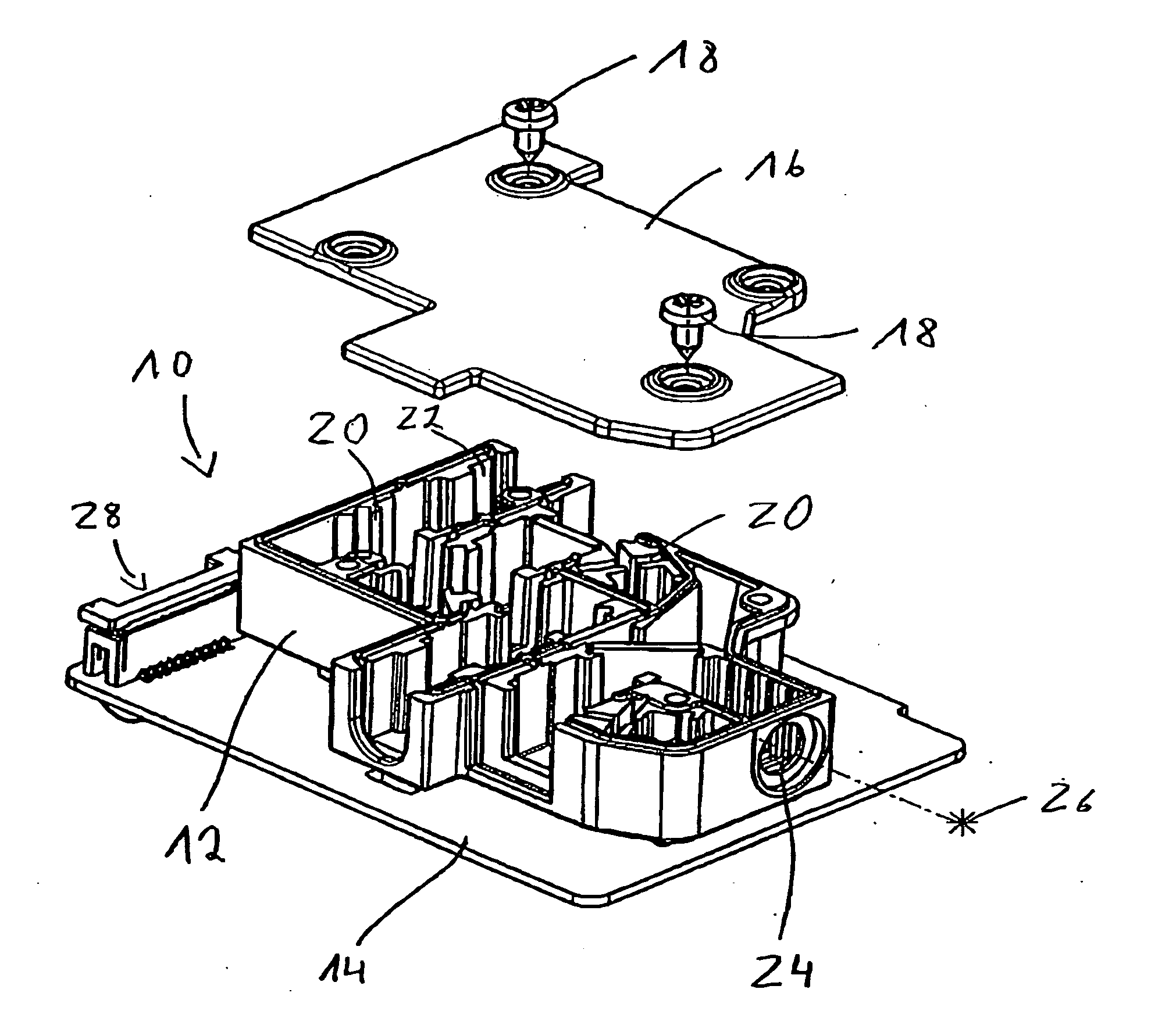
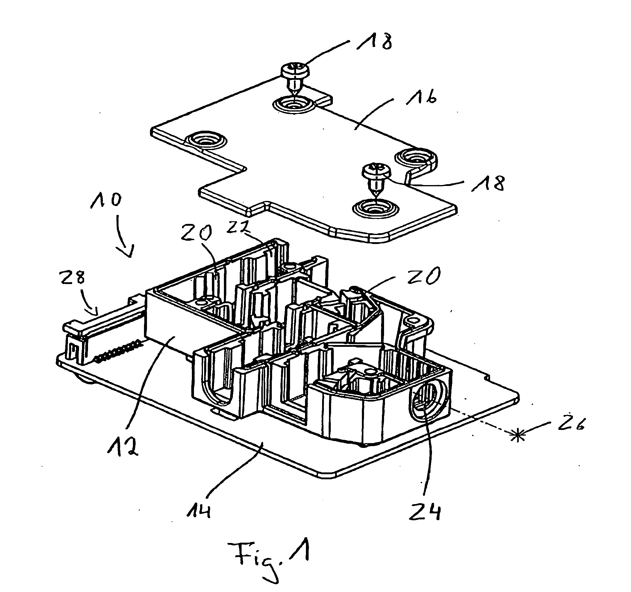
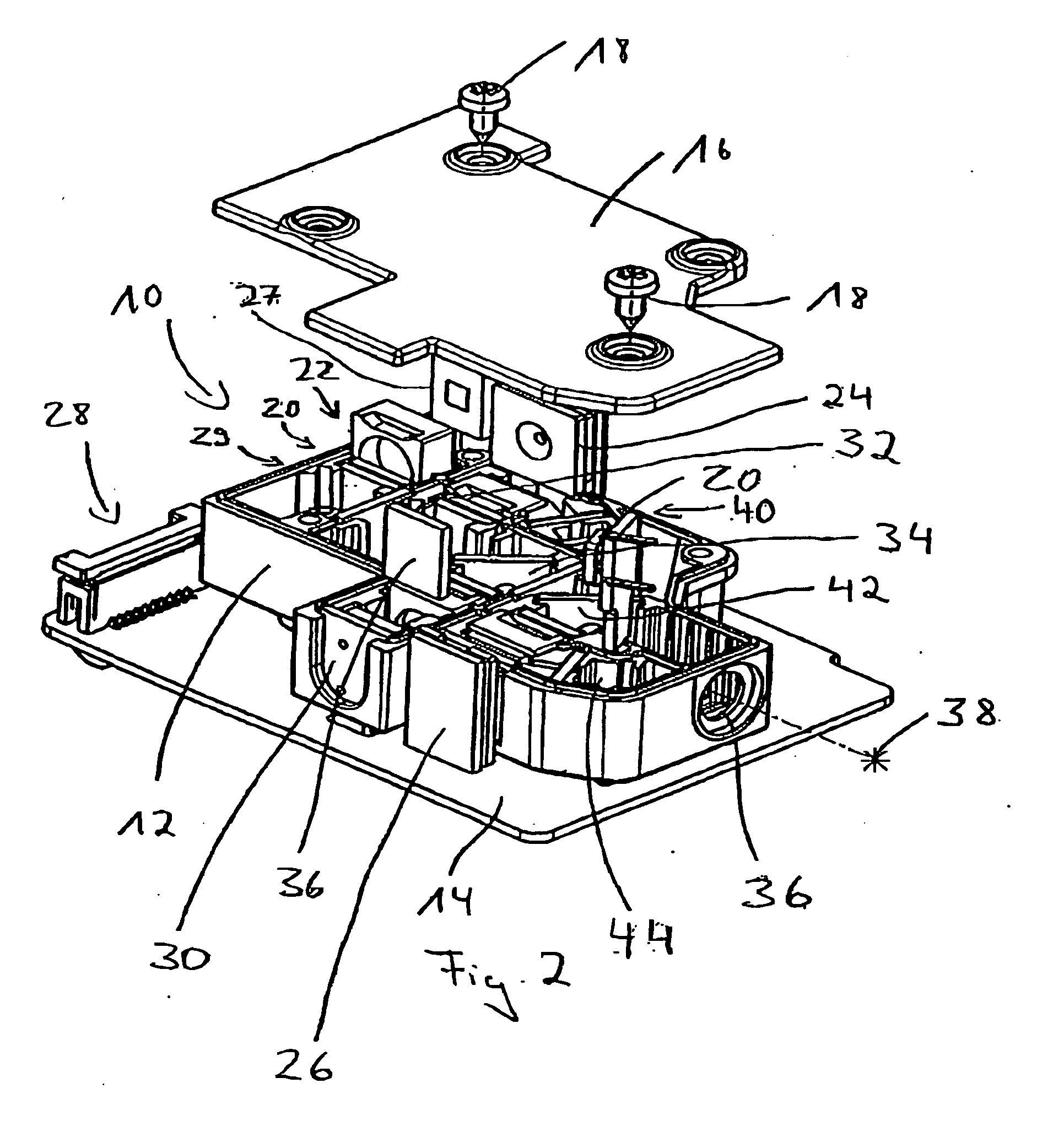
[0024]Furthermore, the mechanical bench allows for secure and exact positioning of various optical components such as filters and mirrors. Thereby, the optical and electronic components can be replaced easily. The optical components can be filters and mirrors. The electronic components perform among others the signal processing. Alternatively, the optical and electronic components can be permanently mounted in the module.
[0026]The confocal measurement does not provide for a high depth of focus but a high sensitivity together with low background noise. Furthermore, the confocal measurement is insensitive to the distance between sample and optics.
[0044]Furthermore, the mechanical bench allows for secure and exact positioning of various optical components such as filters and mirrors. Thereby, the optical and electronic components can be replaced easily. Alternatively, the optical and electronic components can be permanently mounted in the module. The optical components can be filters and mirrors. The electronic components perform among others the signal processing.
[0073]All in all, the invention, at least in the described embodiments provides for customers and users, e.g. in the field of lateral flow immunoassays, several features besides accurate performance: handheld or mobile device, convenient operation and operational robustness, display of positive, negative or invalid test results (for yes / no answers), display of exact quantitative or invalid test results (for quantitative tests), connectivity to USB port, internal memory for a large number of recordings, possibility of adding a printer to the device, possibility of adding calibration data for different batches without a computer, low price, appealing industrial design, to a lesser extend audio visual displays for positive, negative or invalid test results, high throughput function, automated start or repeat of strip recording, kinetic recording of test bands, and wireless transfer.
[0074]The invention provides among others for mobile, pocket sized systems applicable to both, lateral flow and tube formats, for point of test / point of care tests based on fluorescence read-out. These tests work from the sample directly without the need of time consuming sample storage, sample transportation and sample preparation. Examples will be shown for protein as well as nucleic acid based tests and small molecules such as drugs. The core consists of a battery operated, 90 g electrooptical unit with optional wireless data transfer, which has been optimized to achieve highest accuracy and sensitivity paired with simplicity of use.
[0075]The robust systems have been shown to detect as low as 17 nucleic acid molecules (MRSA III) with subtyping specificity in 11 minutes in combination with Molecular Diagnostics techniques. The mobile devices demonstrated precise results from whole blood and Urine to the fully documented data within the low minute range for infectious diseases and drug testing using lateral flow test strips. The affordable devices are ideally suited to serve both, point of care and home care markets due to their specificity, speed and simplicity of use as well as specialty applications such as manned space flight due to their low weight and size.

Problems solved by technology

However, as every technology, lateral flow immunoassays also have limitations and do lack important features to further exploit this technology.
Those are mainly lack of automated documentation, subjective interpretation of results leading to a high number of false positives and false negatives, lack of accurate quantitation and limited multiplexing capabilities as well as limitation in high throughput diagnostics due to manual operation.
Also specificity is influenced by the cross-reactivity of antibodies and limits the applicability to good and stable compounds.
Due to the high demand, the low number of affordable and high performance lateral flow immunoassay devices both for lab and field based tests is surprising: Although lateral flow immunoassays are very affordable since the read out can be performed visually without devices in Gold or Latex Bead based assays, inconvenience in manual documentation and subjective interpretation of results often leading to false negative and false positive results have created high demand for automated systems.
However, there are limitations regarding the miniaturization of CCD based systems as the camera needs a certain field of view to capture the image from the entire strip.
This may result in very limited internal memory capacity or is accordingly expensive.
The disadvantage of scanning systems is however, that it is harder to scan the entire strip and no image of the test strip will be available.
Another disadvantage of scanning systems are their moving parts, which may be subject to failure particularly over longer life-times.
Furthermore, emergency diagnostics, epidemiological preparedness and the high cost of the Health Care System have pushed demand for affordable and mobile point of care devices with highest sensitivity, specificity and short time to result.

Method used


Image

  • Optical measuring instrument
  • Optical measuring instrument
  • Optical measuring instrument

Examples


first embodiment

[0114]FIG. 3 shows an optical measuring instrument 50 according to the invention.

[0115]This measuring instrument 50 comprises a monolithic electrooptical module 52 comprising the optical and electronic parts for performing a measurement. This module 52 corresponds to the module 10 in FIGS. 1 and 2.

[0116]Furthermore, the instrument 50 comprises a sample holder 54 for receiving a sample 56 which is in this case a laminar flow device.

[0117]The sample 56 can be inserted into the sample holder 54 and can be moved relatively to the module 52. Additionally, the module 52 can be moved relatively to the sample 56.

[0118]Moreover, the instrument 50 is provided with a key pad 58 for controlling the measurement and a display 60 for showing the obtained results of the measurement.

[0119]Generally, the instrument comprises a main body 62 and the sample holder 54 connected to each other. The main body 62 includes the key pad 58 and the display 60 and remains basically the same for all types of sampl...


PUM


Abstract

The invention provides for an optical measuring instrument and measuring device. The optical measuring instrument for investigating a specimen contained in a sample comprises at least one source for providing at least one electromagnetic beam intended to irradiate the sample and to interact with the specimen within the sample, at least one sensor for detecting an output of the interaction between the specimen and the electromagnetic beam, an integrally formed mechanical bench for the optical and electronic components, a sample holder for holding the sample, wherein the at least one source, the at least one sensor, and the mechanical bench are integrated in one monolithic optoelectronic module and the sample holder can be connected to this module.

Description

FIELD OF THE INVENTION[0001]The present invention relates to an optical measuring instrument and an optical measuring device. Furthermore, the invention provides for a method for performing an optical measurement and a computer program for carrying out this method.DESCRIPTION OF THE RELATED ART[0002]Optical measuring instruments and methods for performing an optical measurement are known.[0003]Lateral Flow Immunoassays as an example for an optical measurement technique have become invaluable tools for various diagnostics applications in the past. Among the most prominent reasons for this development are that these tools demonstrate reasonable sensitivity and specificity for many applications and provide fast time to result since they are applied to the sample directly often without the need of prior time-consuming sample preparation steps. Lateral Flow Immunoassays are easy to operate and last but not least they do not require a device for read-out, therefore they are cheap and mobi...

Claims


Application Information

Patent Timeline
IPC IPC(8): G01N21/01G01N1/10G01N21/55G01T1/10
CPCG01N21/255G01N21/645G01N2201/024G01N2201/0228G01N21/8483
Inventor GRULER, ROMANFAULSTICH, KONRAD
Owner QIAGEN LAKE CONSTANCE GMBH
Learn More