Method of Forming Insulation Film by Modified PEALD

a technology of insulation film and peal, which is applied in the field of forming insulation film by plasma, can solve the problems of low film growth rate, difficult throughput, and poor coverage of ald, and achieve good coverage, high throughput, and increase the film growth rate

Active Publication Date: 2010-05-20
ASM JAPAN
View PDF10 Cites 498 Cited by
  • Summary
  • Abstract
  • Description
  • Claims
  • Application Information

AI Technical Summary

Benefits of technology

[0006]In some embodiments of the present invention, the film growth rate is increased while maintaining a good coverage, to achieve a high throughput. In other words, the material is broken down using a plasma into, say, a more active material having a smaller molecular weight and thereby increase the amount of material adsorbed to the surface, because then the film growth rate of ALD can be raised. In ad

Problems solved by technology

ALD is a method of forming a film that offers a great coverage, but it presents a challenge in terms of throughput.
On the other hand, CVD can achieve high film growth rates, but its coverage is not as good as what can be achieved with ALD.
However, this reaction only involves the adsorbed material and thus the film growth rate is low.
If the activation

Method used


Image

  • Method of Forming Insulation Film by Modified PEALD
  • Method of Forming Insulation Film by Modified PEALD
  • Method of Forming Insulation Film by Modified PEALD

Examples


example 1

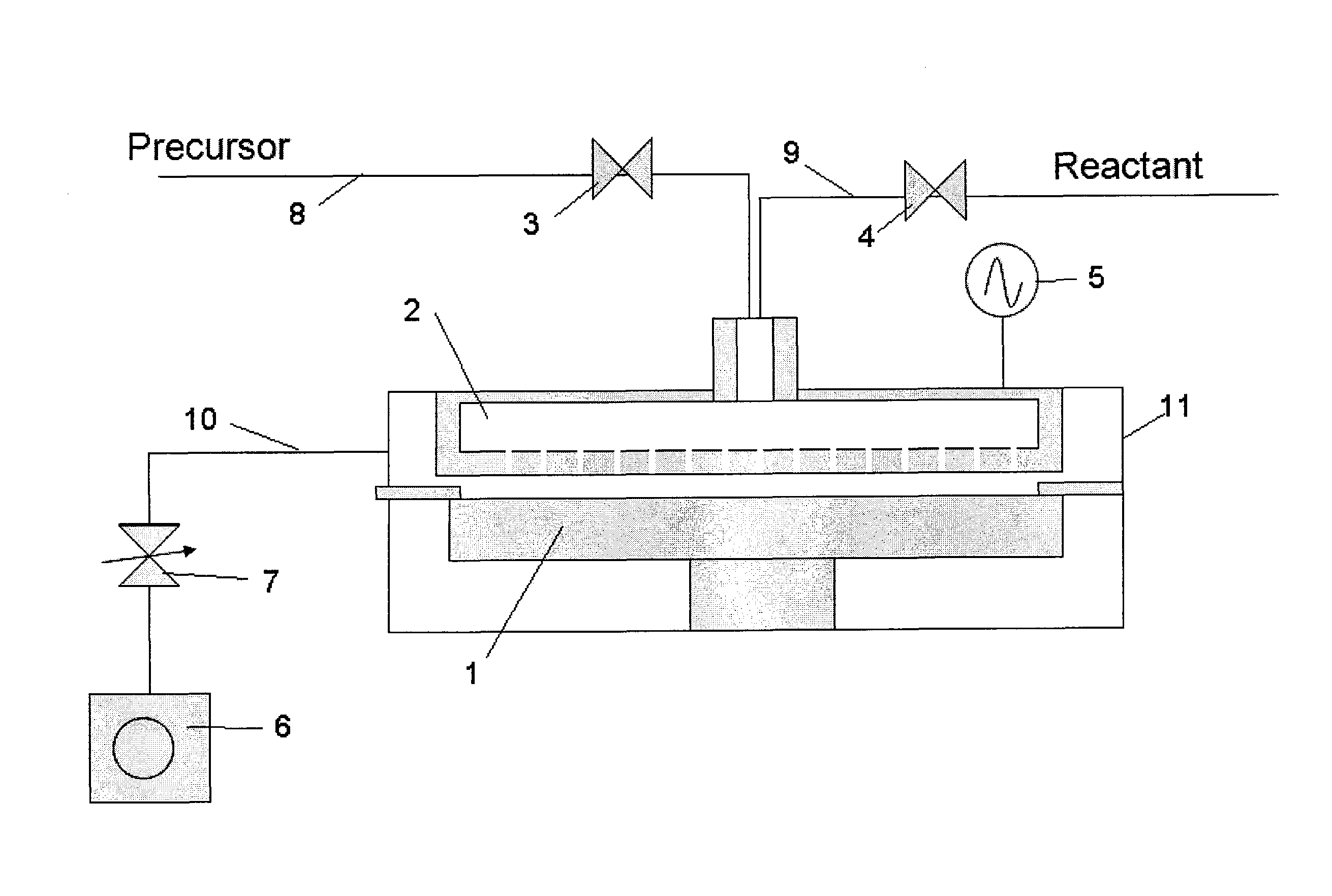
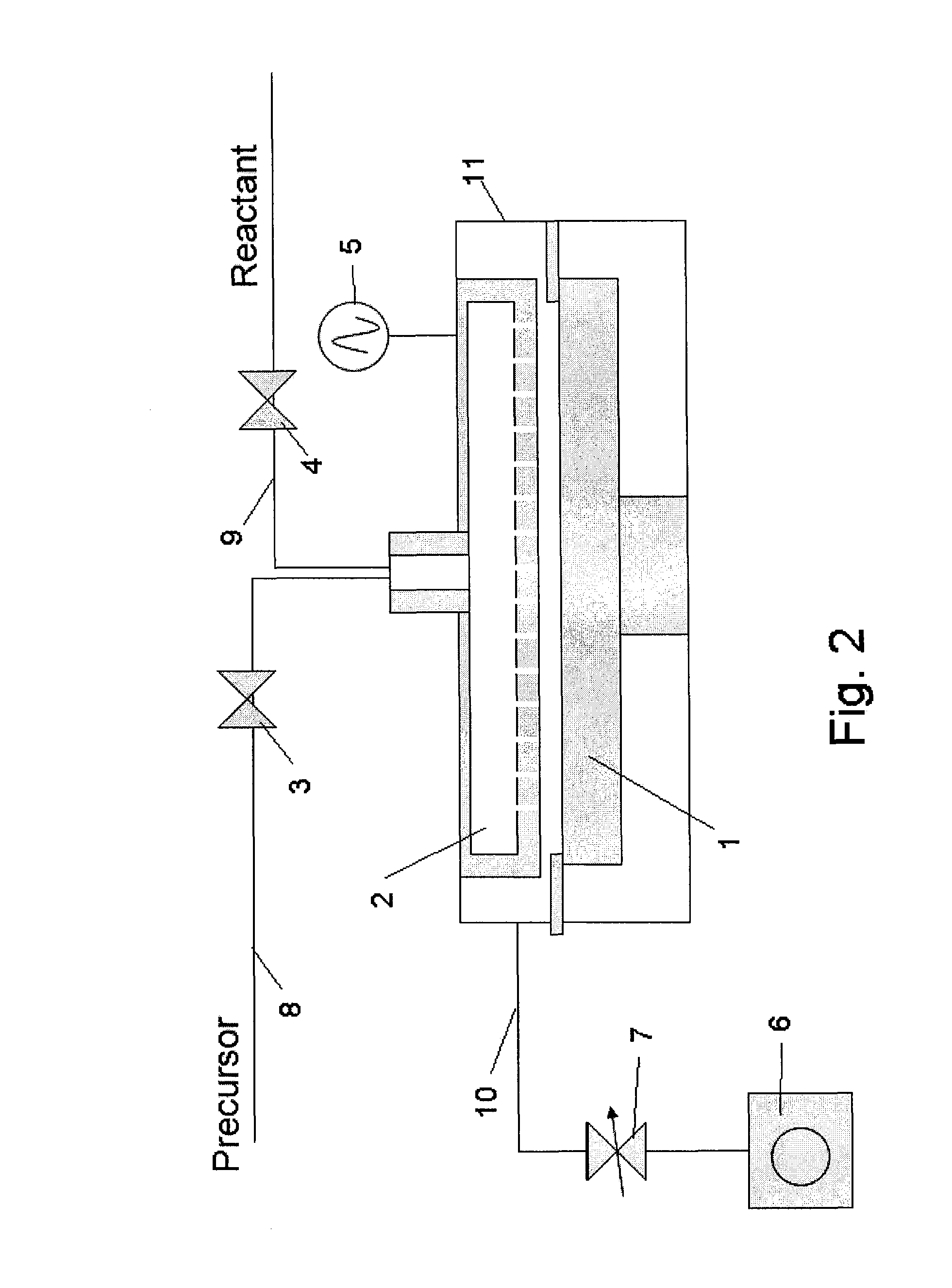
[0077]In this example, the apparatus shown in the schematic diagram of FIG. 2 was used to form a film. This apparatus comprises a reactor 11 which can be retained in a vacuum state, susceptor 1 with heating mechanism used to hold a wafer on top, shower head 2 which provides a mechanism for supplying gas, RF application mechanism 5 that generates a plasma between the shower head and susceptor, material gas supply line 8 equipped with an open / close valve 3 connected to the shower head 2, reactant gas supply line 9 equipped with another open / close valve 4, exhaust line 10 used to exhaust the atmosphere inside the reactor 11, and vacuum pump 6 connected after the exhaust line via a pressure control valve 7, among others. Note that a purge gas line (not illustrated) is also connected to the shower head 2 just like the reactant gas supply line 9.

[0078]A Si wafer (300 mm in diameter) is heated to 400° C., and then HEAD Si2[NHC2H6]6 being the first material, N2 being the reactant gas, as we...

example 2

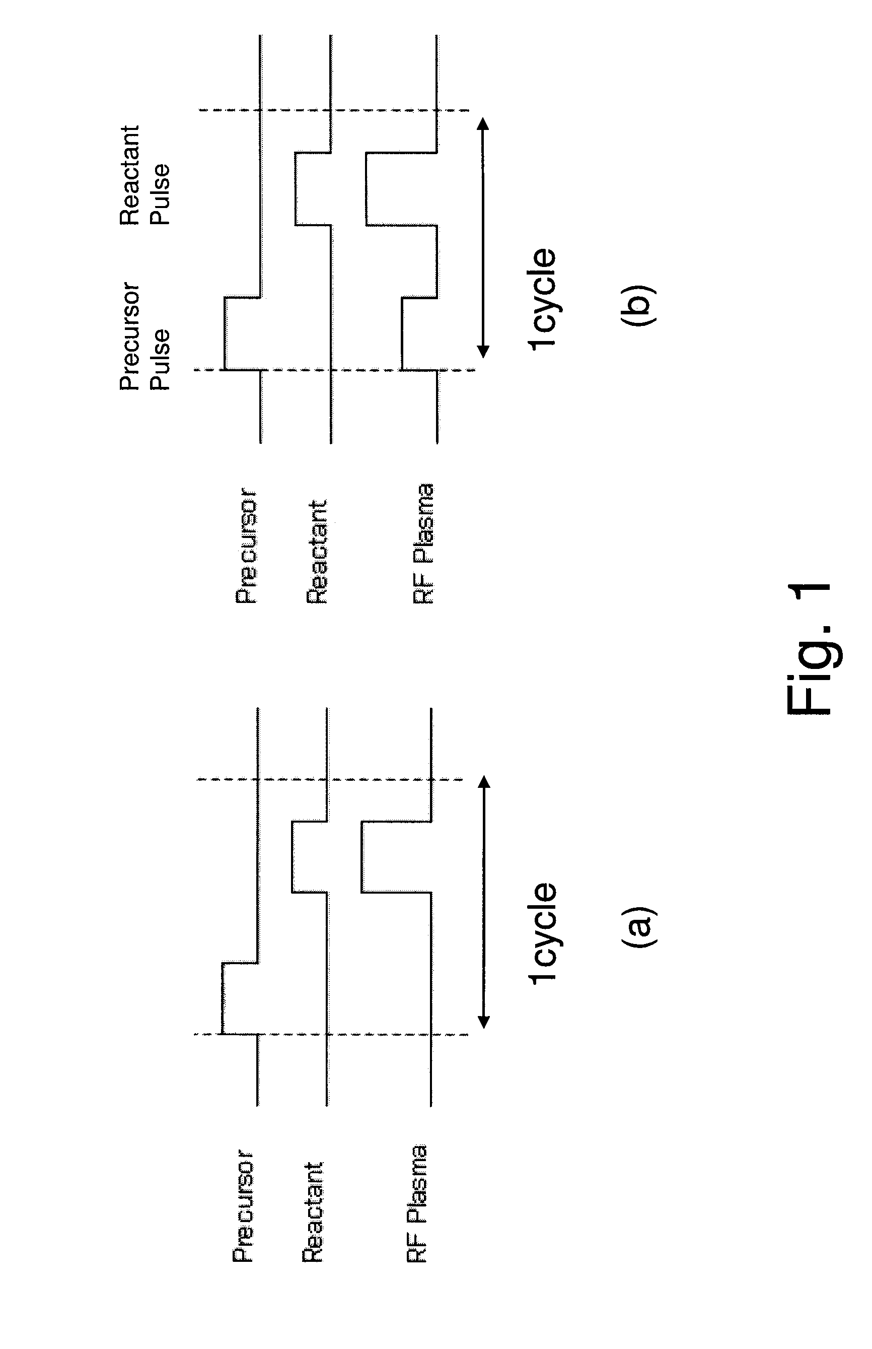
[0085]In accordance with Example 1, a SiO2 film was formed using BDEAS(bis(diethylamino)silane, SiH2[N(C2H5)2]2 as the first material and O2 (900 sccm, supplied for 1 sec) as the reactant gas. Therefore, when a conventional PEALD sequence (FIG. 1 (a)), was used, the film growth rate was 0.1 nm / cycle. On the other hand, use of a sequence (FIG. 1 (b)) similar to the one explained in Example 1, where RF was applied by 10 W in the material supply process and by 300 W in the reactant gas supply process boosted the film growth rate to 0.25 nm / cycle. A good coverage was also achieved (98%). However, application of 80 W in the aforementioned material supply process resulted in a film growth rate of 1 nm / cycle and the coverage also dropped (80%).

[0086]Further, the film growth rate increased to 5 nm / cycle when RF was applied by 20 W in the first material process while O2, being the reactant gas, was being supplied (by 300 sccm). However, this led to generation of particles also at the shower ...

example 3

[0087]In accordance with Example 1, a film was formed in the same manner as in Example 1, except that 3EMAS (tris(ethylmethylamino)silane, H2Si[N(C2H5)CH3]3 was used as the first material, 3EMAS was supplied simultaneously with the first reactant gas N2 (300 sccm), RF was applied by 30 W, and then RF was turned off and the atmosphere was purged, followed by supply of the second reactant gas H2 (500 sccm) and application of RF by 500 W. As a result, or specifically as a result of applying the reactant gases and RF in the first material supply process, the film growth rate increased (achieved film growth rate=0.1 nm / cycle).


PUM

PropertyMeasurementUnit
Pressureaaaaaaaaaa
Timeaaaaaaaaaa
Timeaaaaaaaaaa

Abstract

A method of forming an insulation film by alternating multiple times, respectively, a process of adsorbing a precursor onto a substrate and a process of treating the adsorbed surface using reactant gas and a plasma, wherein a plasma is applied in the process of supplying the precursor.

Description

CROSS REFERENCE TO RELATED APPLICATIONS[0001]This application claims the benefit of U.S. Provisional Application No. 61 / 114,847, filed Nov. 14, 2008, and the disclosure of which is herein incorporated by reference in its entirety.BACKGROUND[0002]1. Field of the Invention[0003]The present invention generally relates to a method of forming an insulation film by plasma enhanced atomic layer deposition (PEALD).[0004]2. Description of the Related Art[0005]ALD is a method of forming a film that offers a great coverage, but it presents a challenge in terms of throughput. On the other hand, CVD can achieve high film growth rates, but its coverage is not as good as what can be achieved with ALD. Conventional PEALD is a method whereby the first key material is adsorbed to the surface of the target and then a reactant gas that has been activated by a plasma is supplied to cause surface reaction with the adsorbed material (refer to US2005 / 0037154 A1, for example). Since what is occurring is sur...

Claims


Application Information

Patent Timeline
IPC IPC(8): C23C16/48
CPCC23C16/325C23C16/345C23C16/402C23C16/45542C23C16/45553H01L21/0228H01L21/02164H01L21/0217H01L21/02219H01L21/02274H01L21/0214
Inventor KOBAYASHI, AKIKOSHIMIZU, AKIRAKOBAYASHI, NOBUYOSHILEE, WOO-JIN
Owner ASM JAPAN
Why Eureka
Try Eureka