Joint support and subchondral support system

a joint support and subchondral technology, applied in the field of joint support and subchondral support system, can solve the problems of inferior resultant material to native cartilage, large lesions, and unresolved diffuse diseases, and achieve the effect of enhancing the ability of trabecular bone to withstand and increasing thickness

Inactive Publication Date: 2010-06-10
DEE DEREK
View PDF58 Cites 67 Cited by
  • Summary
  • Abstract
  • Description
  • Claims
  • Application Information

AI Technical Summary

Benefits of technology

[0013]The contoured, porous plate is configured to fit flush with at least one contour of the corresponding subchondral bone at the specific body location to be treated, or it may be of reverse, neutral or complex polarity. The contoured plate may be inserted in at least two locations of the subchondral bone as a modular or monobloc insert. At least two contoured, porous plates may be placed anterior and posterior to each other within the subchondral bone. The contoured, porous plate has a cross-sectional area of from about 1 mm2 to about 100 cm2. The peripheral surface has a variable thickness of from about 0.1 mm to about 5 cm. The central area of the plate may be of a thinner dimension, with a reverse taper to increase thickness peripherally.
[0014]The contoured, porous pl...

Problems solved by technology

Microfracture or abrasionplasty is a form of irritating exposed bone to create replacement fibrocartilage, but the resultant material is inferior to native cartilage.
Small discrete lesions work well, but larger lesions, bipolar disease, and diffuse disease are not well addressed.
Less optimal results occur with patellofemoral joint disease, and tibial sided disease.
Osteotomy also complicates latter joint replacement.
This type of procedure presents a prolonged recovery time and surgical risks.
Because total joint prostheses are fabricated of metal and plastic, revision surgery for worn-out components is fraught with much higher complicat...

Method used


Image

  • Joint support and subchondral support system
  • Joint support and subchondral support system
  • Joint support and subchondral support system

Examples


Embodiment Construction

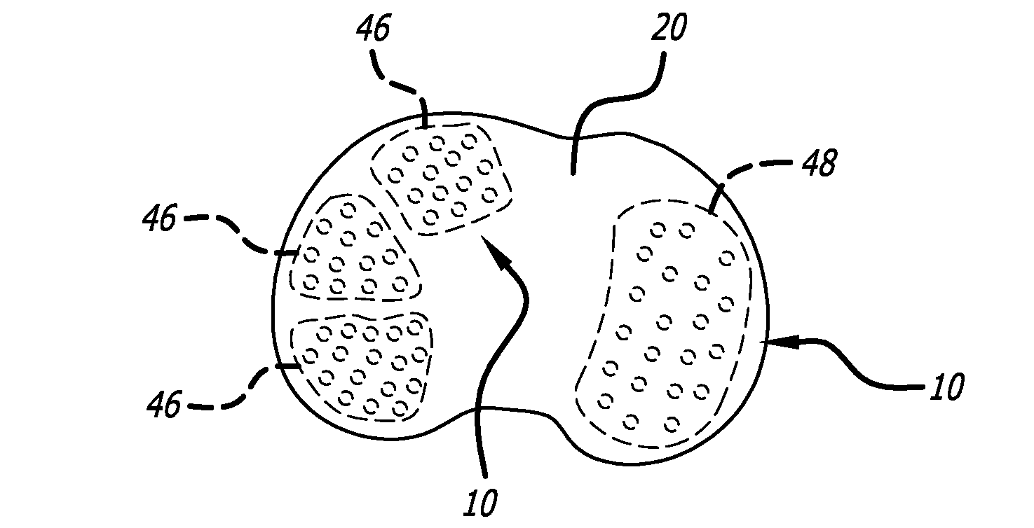
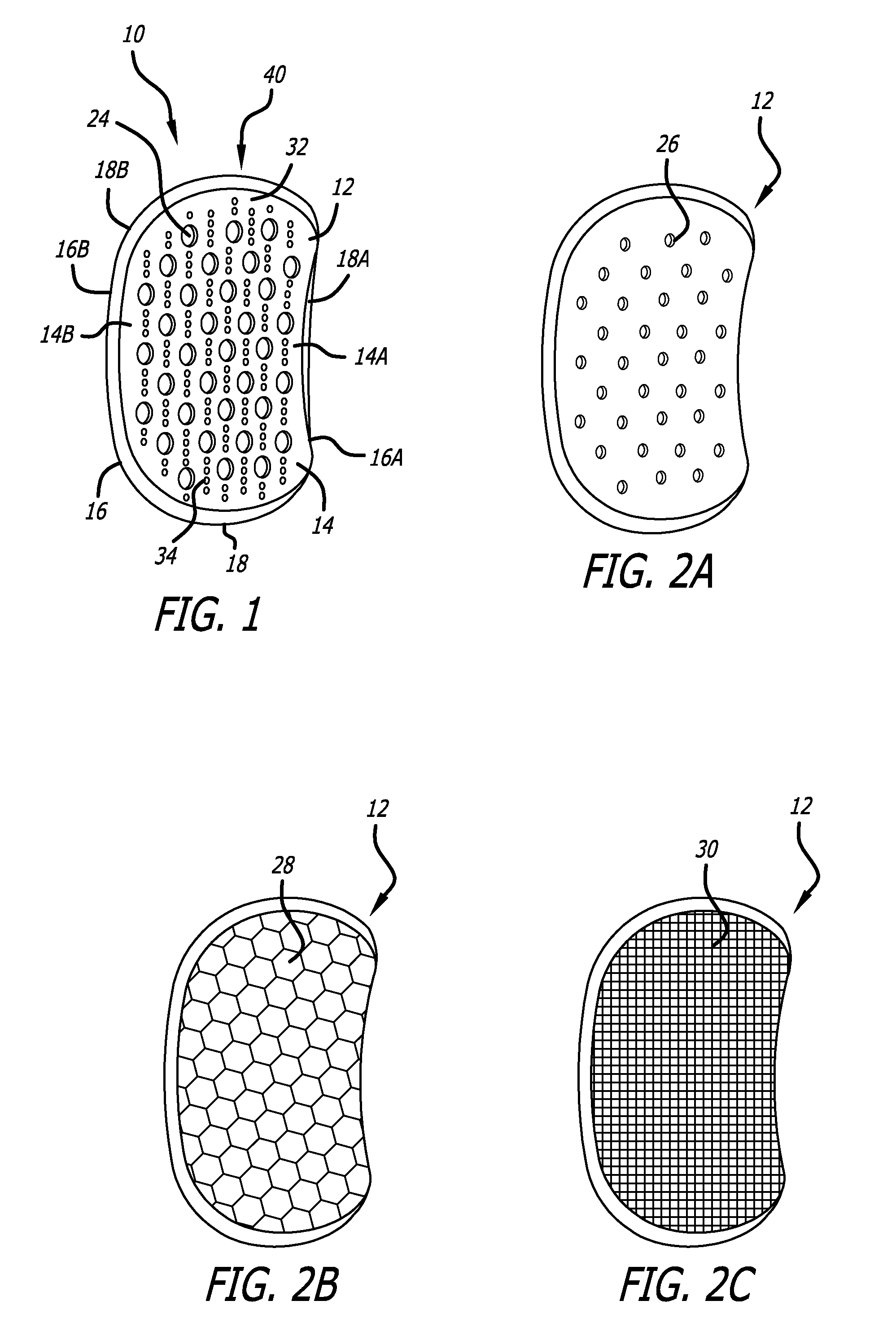
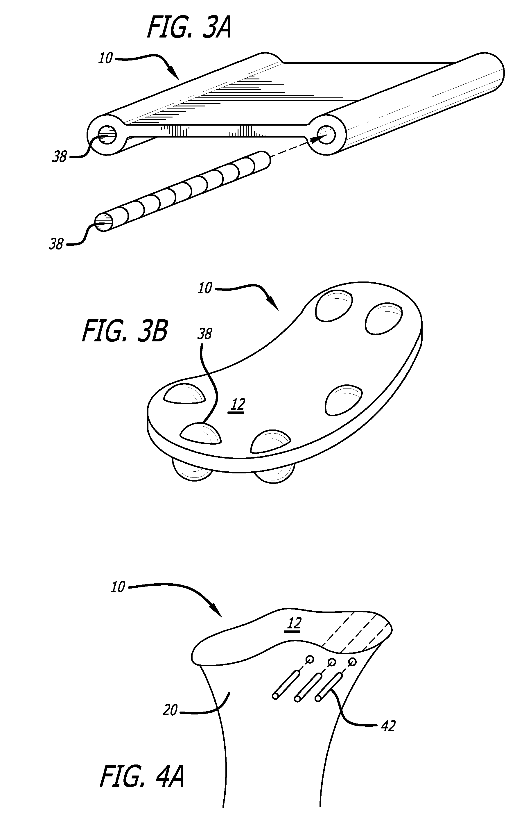
[0074]The joint support and subchondral support system or device 10 of the present invention is generally illustrated in FIG. 1. It is contemplated by the present invention that the joint support and subchondral support system is not a substitute for partial or total joint replacement, but may delay the need for joint replacement in active individuals with moderate osteoarthritis and / or arthroses. By sustaining subchondral bone homeostases, further joint deformity and disease progression may be delayed and / or avoided. The joint support and subchondral support system in accordance with the present invention enhances and reinforces the cartilage-bone complex in the presence of diseased cartilage or a cartilage defect. It treats the bony side of the equation by mechanical absorption of shear and compressive stresses that threaten cartilage-bone homeostasis.

[0075]A number of advantages of the joint support and subchondral support system in accordance with the present invention are e...


PUM


Abstract

A joint support and subchondral support system for providing structural and dampening support to damaged subchondral bone in generalized or discrete arthritis includes a contoured, porous plate having a variable shaped inner surface, outer surface, and peripheral surface of variable thickness extending between the inner surface and the outer surface, suitable for insertion within the subchondral bone. The inner surface, outer surface and peripheral surface each have a concave portion and a convex portion. A guide pin hole or slot is located within the contoured, porous plate to aid in insertion and placement of the plate over at least one corresponding guide pin within the subchondral bone. The joint support and subchondral support system of the present invention is applicable to many parts of the joint as any area with cartilage disease has an adjoining subchondral component.

Description

[0001]Cartilage disease has been previously addressed by various means of replacing or substituting the damaged cartilage. Microfracture or abrasionplasty is a form of irritating exposed bone to create replacement fibrocartilage, but the resultant material is inferior to native cartilage. Osteochondral transplant replaces plugs of diseased cartilage and accompanying subchondral bone with grafts from either the patient or human cadaver. Small discrete lesions work well, but larger lesions, bipolar disease, and diffuse disease are not well addressed. Chondrocyte implantation harvests the patient's cartilage cells, grows them, and re-implants them on the bony bed, and covers them with a periosteal patch. Each of the aforementioned techniques work best for small contained lesions, unipolar defects (i.e., one side of joint), and primarily femoral condyle lesions. Less optimal results occur with patellofemoral joint disease, and tibial sided disease.[0002]A further method of treating cart...

Claims


Application Information

Patent Timeline
IPC IPC(8): A61F2/08
CPCA61F2/30756A61F2/38A61F2/389A61F2002/2892A61F2002/3895A61F2002/2825A61F2002/30845A61F2002/30131A61F2002/30563A61F2/3859A61F2002/30759A61F2002/30841A61B17/562A61F2/30A61F2002/30171
Inventor DEE, DEREK
Owner DEE DEREK
Why Eureka
Try Eureka