Method of Grooving Superalloys and Cutting Insert Therefor

a cutting insert and superalloy technology, applied in the field of grooving superalloys and cutting inserts therefor, can solve the problems of high difficulty in shaping and machined inconel and other superalloys, unsatisfactory performance of other materials such as aluminum or steel in such applications, undesired plastic and elastic deformation of various areas, etc., to achieve the maximum cutting speed of inconel, improve the performance of grooving superallo

Active Publication Date: 2010-07-15
ISCAR LTD
View PDF72 Cites 26 Cited by
  • Summary
  • Abstract
  • Description
  • Claims
  • Application Information

AI Technical Summary

Benefits of technology

[0010]In some embodiments, for example, a combination, or a partial combination of the following—covering the cutting insert with the CBN layer, directing coolant fluid directly on the interaction area through the interior ducts, and the proximity of the interior ducts to the interaction area—provides a significantly improved performance of grooving superalloys, compared to the prior art. By virtue of this combination or partial combination, the method may include grooving an Inconel work-piece at cutting speeds (Vcs) of 200-500 meters per minute, achieving good to excellent surface quality and chip formation, e.g., achieving formation of chips in the length range of 1-5 millimeters. These improved cutting speeds achieved using the method, significantly exceed, i.e., by tens to hundreds of percents, the maximal cutting speed of Inconel that is obtainable in the prior art. The method thereby introduces significant reduction in costs of machining Inconel and other superalloys.

Problems solved by technology

Therefore, Inconel retains its strength over a wide range of temperatures and is attractive for use in high temperature applications, whereas other materials such as aluminum or steel perform unsatisfactorily in such applications.
Nevertheless, Inconel and other superalloys are highly difficult to shape and machine, e.g., due to their rapid work-hardening during the machining process.
For example, after completion of a first machine pass on a work-piece of Inconel, the rapid work-hardening causes, in subsequent machine passes, undesired plastic and elastic deformations of various areas of the work-piece that come into interaction with the cutting tool.
However, the present solution including providing of coolant fluid, for example, using known cemented carbide cutting inserts, limits the cutting speed (Vc) of the work-piece to approximately 40-60 meters per minute, which is a relatively limited cutting speed, compared to cutting speeds of other cutting operations.
For example, the low cutting speed leads to high machining costs and thus to high manufacturing costs.

Method used


Image

  • Method of Grooving Superalloys and Cutting Insert Therefor
  • Method of Grooving Superalloys and Cutting Insert Therefor
  • Method of Grooving Superalloys and Cutting Insert Therefor

Examples


Embodiment Construction

[0022]In the following description, various aspects of the present invention will be described. For purposes of explanation, specific configurations and details are set forth in order to provide a thorough understanding of the present invention. However, it will also be apparent to one skilled in the art that the present invention may be practiced without the specific details presented herein. Furthermore, well-known features may be omitted or simplified in order not to obscure the present invention.

[0023]Although some descriptions herein refer to a method and / or to a cutting insert for machining Inconel, the present invention is not limited in this respect. For example, some embodiments of the invention may refer to grooving of other superalloys, of ordinary metal alloys, of high-temperature alloys, of other nickel based alloys, or the like.

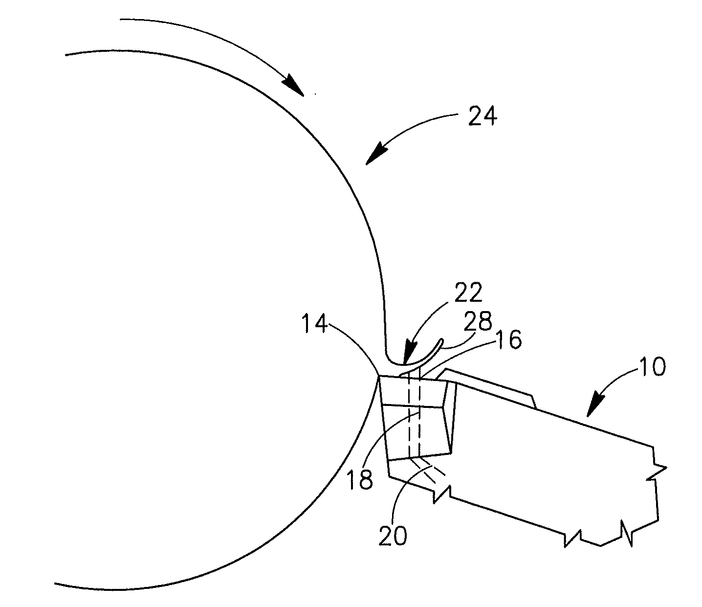
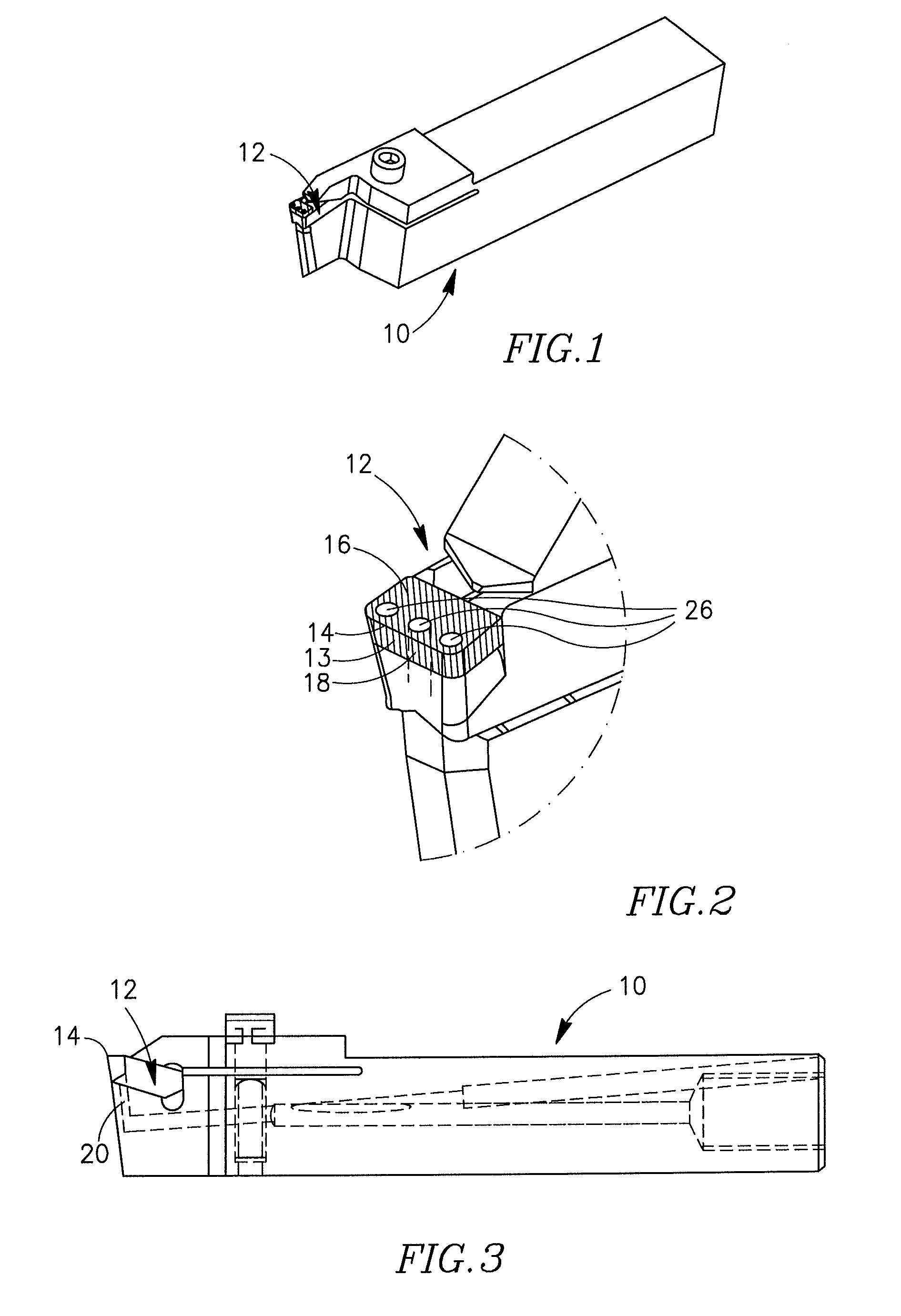
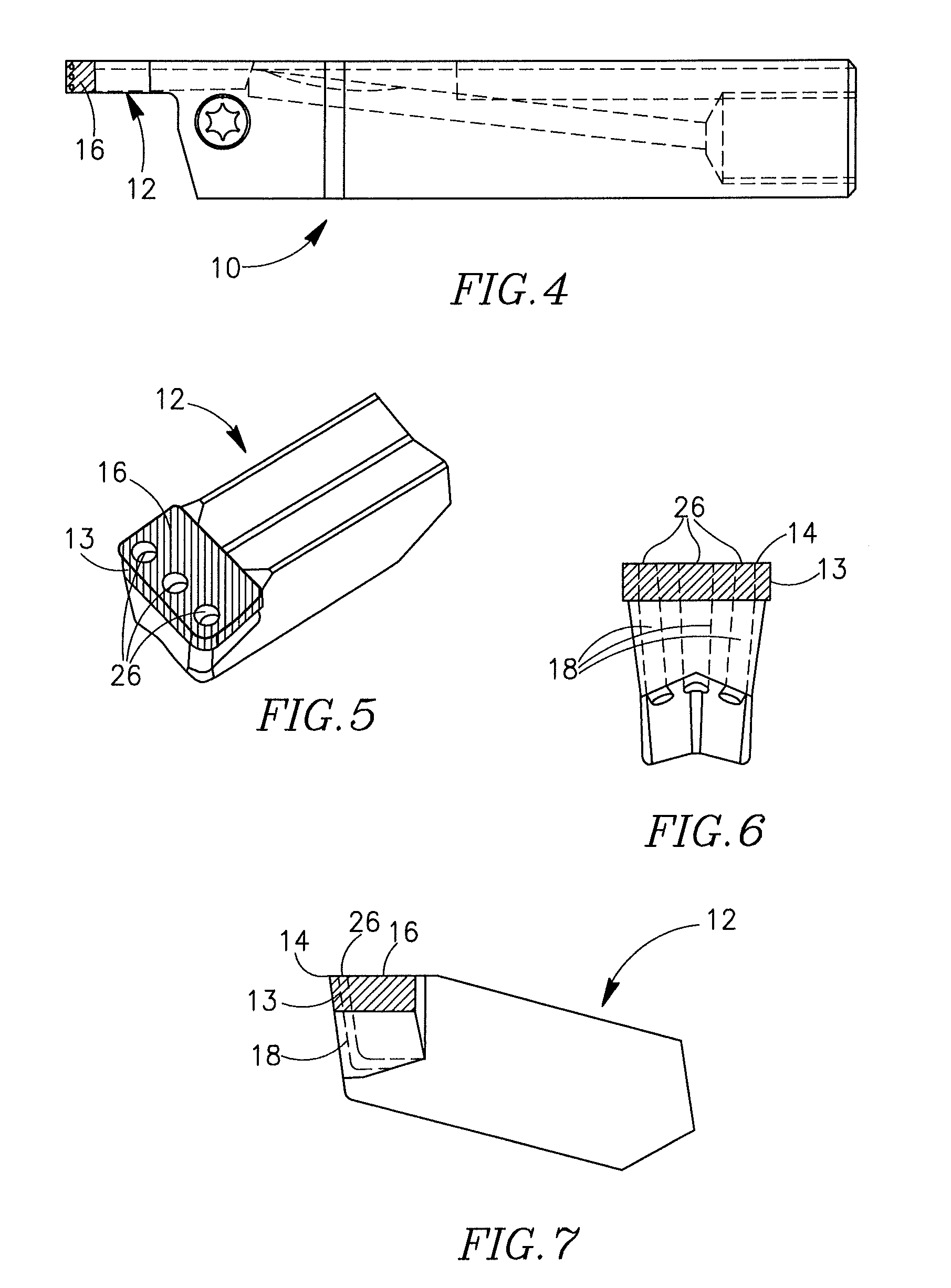
[0024]Reference is made to FIGS. 1-9, showing various views of a cutting tool 10 having a grooving cutting insert 12 releasably retained therei...


PUM

PropertyMeasurementUnit
pressureaaaaaaaaaa
lengthsaaaaaaaaaa
pressureaaaaaaaaaa

Abstract

A method of grooving a work-piece of superalloy uses a grooving cutting insert at least partially covered with a Cubic Boron Nitride (CBN) layer and having one or more interior ducts formed therein which open out to the insert's rake face at one or more corresponding openings. One or more coolant fluid streams, conveyed via these interior ducts at a pressure of no less than 200 bars, are directed upwardly and outwardly toward an interaction area between a cutting edge of the cutting insert and the work-piece, to thereby limit lengths of work-piece chips created during the grooving operation. The openings of the cutting insert's interior ducts may be located between 0.5-3.0 mm from the insert's cutting edge.

Description

FIELD OF THE INVENTION[0001]The present invention relates to a method of machining superalloys, for example, Inconel, and to a cutting insert for performing the method.BACKGROUND OF THE INVENTION[0002]Superalloys have been used in the metal industry for many years. A superalloy or a high-performance alloy is a metal alloy that exhibits excellent mechanical strength and creep resistance, e.g., at high temperatures, high surface stability, and high resistance to corrosion and oxidation. Superalloys typically have an austenitic, face-centered, cubic crystal structure. Alloying elements of superalloys usually include nickel, cobalt, or nickel-iron. Superalloy development relies on chemical and process innovations, and is driven primarily by the aerospace industry and by power industries such as the industrial gas-turbine and marine-turbine industries.[0003]Examples of superalloys are Hasteloy, Waspaloy, Rene alloys (e.g., Rene 41, Rene 80, Rene 95), Haynes alloys, Incoloy, single crysta...

Claims


Application Information

Patent Timeline
Patent Type & Authority Applications(United States)
IPC IPC(8): B23B3/00B23P15/28
CPCY10T407/14Y10T407/23B23B29/043B23B2228/10Y10T82/10B23B27/045Y10T407/25B23B2222/36B23B27/10Y10T407/24B23B2226/125B23B2250/12
Inventor DESCHENAUX, PATRICKBRENNER, KURT
Owner ISCAR LTD
Why Eureka
Try Eureka