Method For Providing An Implantable Electrical Lead Wire

a technology of electrical lead wires and lead wires, which is applied in the field of implantable electrical lead wires, can solve the problems of loss of the fatigue resistance of nickel, cobalt, chromium and molybdenum materials and their alloys, damage during the coating process, and general poor adhesion of the wires, so as to prevent the degradation of polyurethane insulators, good hardness, durability, and adhesion

Inactive Publication Date: 2010-07-29
WILSON GREATBATCH LTD
View PDF15 Cites 1 Cited by
  • Summary
  • Abstract
  • Description
  • Claims
  • Application Information

AI Technical Summary

Benefits of technology

[0011]Polyurethane insulator degradation is prevented by means of a barrier coating consisting of a very thin sputtered film of selected metal, ceramic, and carbon in the form of amorphous carbon, turbostratic carbon, diamond-like carbon, and the like. These films are characterized by very good hardness, durability, and adhesion. When applied as a thin film, they readily conform to the lead wire metal surface as the wire is formed into a coil. At very thin film thicknesses, the films readily adapt to the stresses of coiling a wire into a helical shape to provide an effective barrier layer.

Problems solved by technology

The disadvantage is that the very desirable fatigue resistance of nickel, cobalt, chromium, and molybdenum materials and their alloys is lost.
The disadvantage of using titanium and platinum as coating materials, however, is that they can be damaged during the coating process and lead assembly, as well as by the stylet during implantation.
Another disadvantage is their generally poor adhesion to the wire throughout the deformation process during coiling to low diameter coils.
The deformation process can also result in the development of small breaches or cracks in the titanium and platinum coating.
Even in the absence of an insulative outer layer, the typical cracks and breaches in the sputtered coating due to winding are unlikely to produce significant areas of contact between the base metal of the coil and the polyurethane insulation.”
Any degree of compromise in the insulation layer is cause for concern.

Method used


Image

  • Method For Providing An Implantable Electrical Lead Wire
  • Method For Providing An Implantable Electrical Lead Wire
  • Method For Providing An Implantable Electrical Lead Wire

Examples


Embodiment Construction

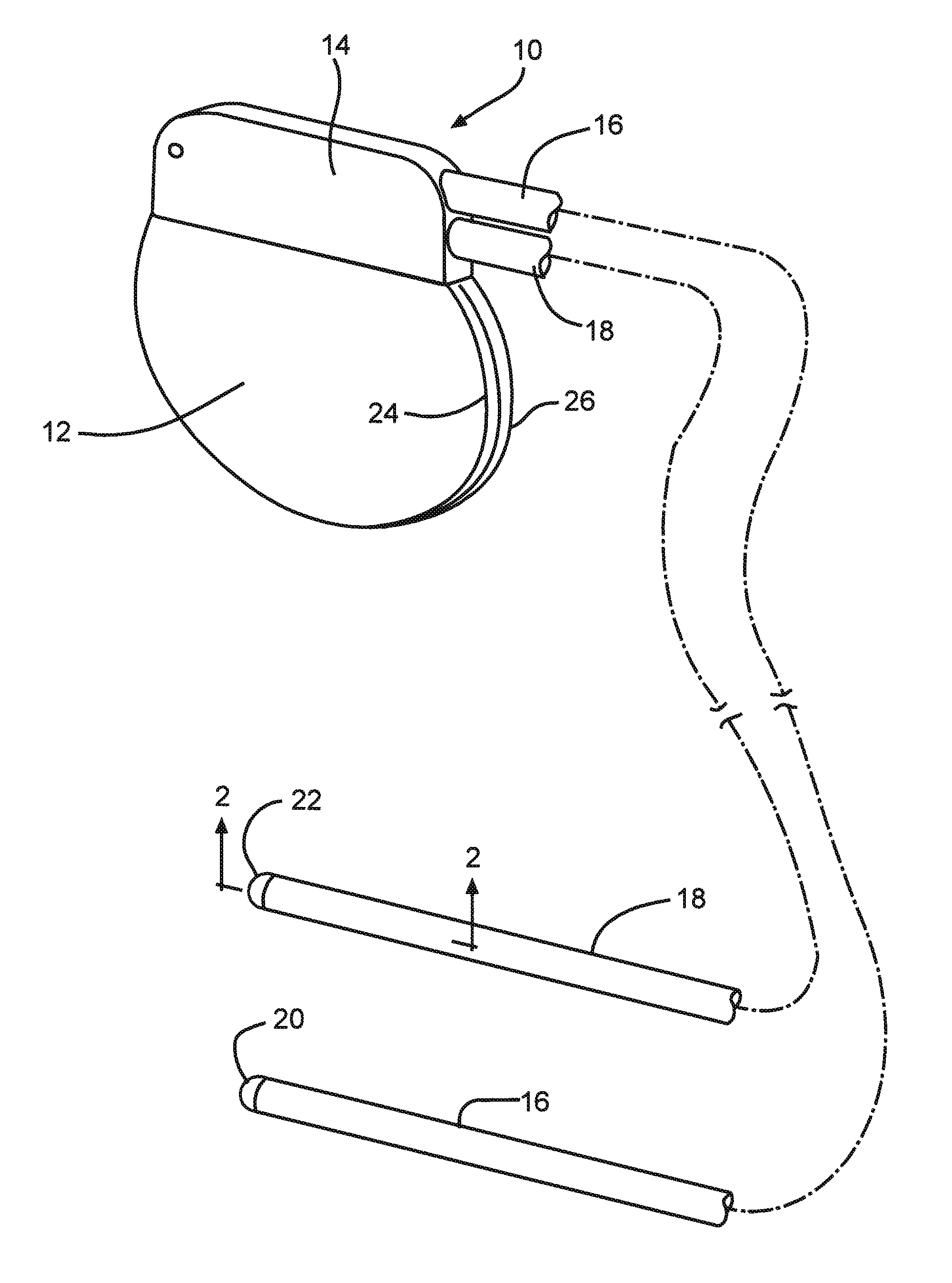
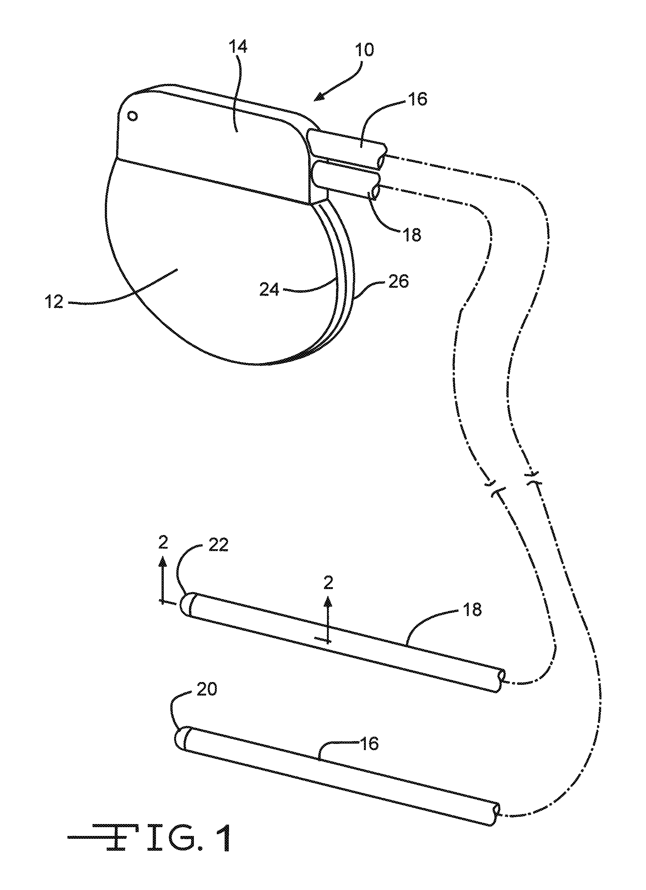
[0016]Referring now to the drawings, FIG. 1 illustrates an implantable medical device 10 comprising a housing 12 supporting a header 14 connecting leads 16 and 18 to respective electrodes 20 and 22. The housing 12 is of a conductive material, such as of titanium or stainless steel. Preferably, the medical device housing 12 comprises mating clamshell portions 24 and 26 in an overlapping relationship. The clamshell housing portions are hermetically sealed together, such as by laser or resistance welding, to provide an enclosure for control circuitry (not shown) connected to a power supply (not shown), such as a battery. There may also be a capacitor for a medical device such as a defibrillator. U.S. Pat. No. 6,613,474 to Frustaci et al. contains a more detailed description of a housing comprising mating clamshell portions. This patent is assigned to the assignee of the present invention and incorporated herein by reference. The housing 12 can also be of a deep drawn, prismatic and cyl...


PUM

PropertyMeasurementUnit
thicknessaaaaaaaaaa
diameteraaaaaaaaaa
diameteraaaaaaaaaa

Abstract

Implantable electrical lead wires, such as cobalt-chromium-molybdenum alloy wires, are coated with a metal, ceramic, or carbon to a thickness of about 100 nm or less to provide a non-reactive interface to polyurethane sheathing materials. Preferred is sputter coating an amorphous carbon intermediate the alloy wire and the polyurethane sheath.

Description

CROSS-REFERENCE TO RELATED APPLICATIONS[0001]This application is a divisional of U.S. application Ser. No. 10 / 969,397, filed Oct. 20, 2004, which claims priority from U.S. Provisional Application Ser. No. 60 / 512,741, filed Oct. 20, 2003.BACKGROUND OF THE INVENTION[0002]1. Field of the Invention[0003]The present invention relates to implantable electrical lead wires such as those used in cardiac pacing and neurostimulation. More particularly, the present invention relates to a solution to the chronic compatibility problems of lead wires with the materials used to insulate them.[0004]The primary requirements of lead wires are conductivity and fatigue resistance. Because lead wires are designed so that body fluids never come into contact with the conductor material, biocompatibility has only been considered a secondary requirement. However, with the introduction of polyurethane as an insulator for lead wires, it is now known that an interaction can be initiated at the conductor / insulat...

Claims


Application Information

Patent Timeline
Patent Type & Authority Applications(United States)
IPC IPC(8): B05D7/00C23C14/34B29C35/08A61N1/05C23C14/56
CPCA61N1/0551Y10T428/2913C23C14/562A61N1/056
Inventor O'BRIEN, ROBERT C.
Owner WILSON GREATBATCH LTD
Why Eureka
Try Eureka