Methods for making membranes based on anodic aluminum oxide structures

Inactive Publication Date: 2010-09-02
INTEGRATED DEVICE TECH INC
View PDF44 Cites 58 Cited by
  • Summary
  • Abstract
  • Description
  • Claims
  • Application Information

AI Technical Summary

Benefits of technology

[0022]Overall, reduction to practice of many AAO-based components and products, especially membranes, is impeded by the lack of methods for making AAO with: (i) large pore period and large-diameter pores in the support layer, which is needed to sustain

Problems solved by technology

However, the production and implementation of such membranes is very challenging.
Although Pd-based bulk foils exhibit near-infinite selectivity for H2, they are expensive and have poor flux due to the high foil thickness required for sufficient mechanical robustness.
However, the total area of the supported Pd membrane was small, limiting the total flux.
Additionally, the Pd windows ruptured when subjected to trans-membrane pressures of about 0.5 bar, and the thermal reliability of the thin Pd film on Si was a problem due to the mismatch of temperature expansion coefficients.
Although thin-film supported membranes, such those described above, have been implemented, their commercial utility has been very limited.
Such membranes have problems related to poor adhesion of the active layer to the porous support, damage to the thin films caused by thermal cycling and susceptibility to damage from mechanical loads and abrasion.
This leads to membrane failures during typical operating conditions.
However, although conventional AAO structures could support a much thinner active layer, the active layer resides on the membrane surface and is prone to hydrogen embrittlement and mechanical damage.
The method does not allow the formation of the active layer disposed entirely within the nanoporous support structure.
Existing liquid filtration membranes, such as polymer membranes, have significant drawbacks limiting their separation performance in many separations applications.
Broad pore size distribution, inherent in the commercial polymer membranes, limits the selectivity of the membranes.
Fouling occurs when proteins adsorb on the membrane surfac

Method used


Image

  • Methods for making membranes based on anodic aluminum oxide structures
  • Methods for making membranes based on anodic aluminum oxide structures
  • Methods for making membranes based on anodic aluminum oxide structures

Examples


Example

Example 1

Free-Standing AAO Structures

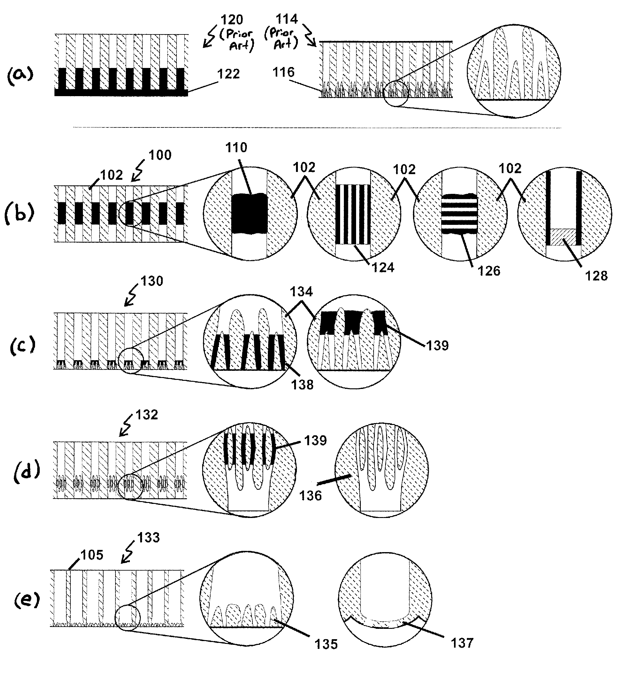
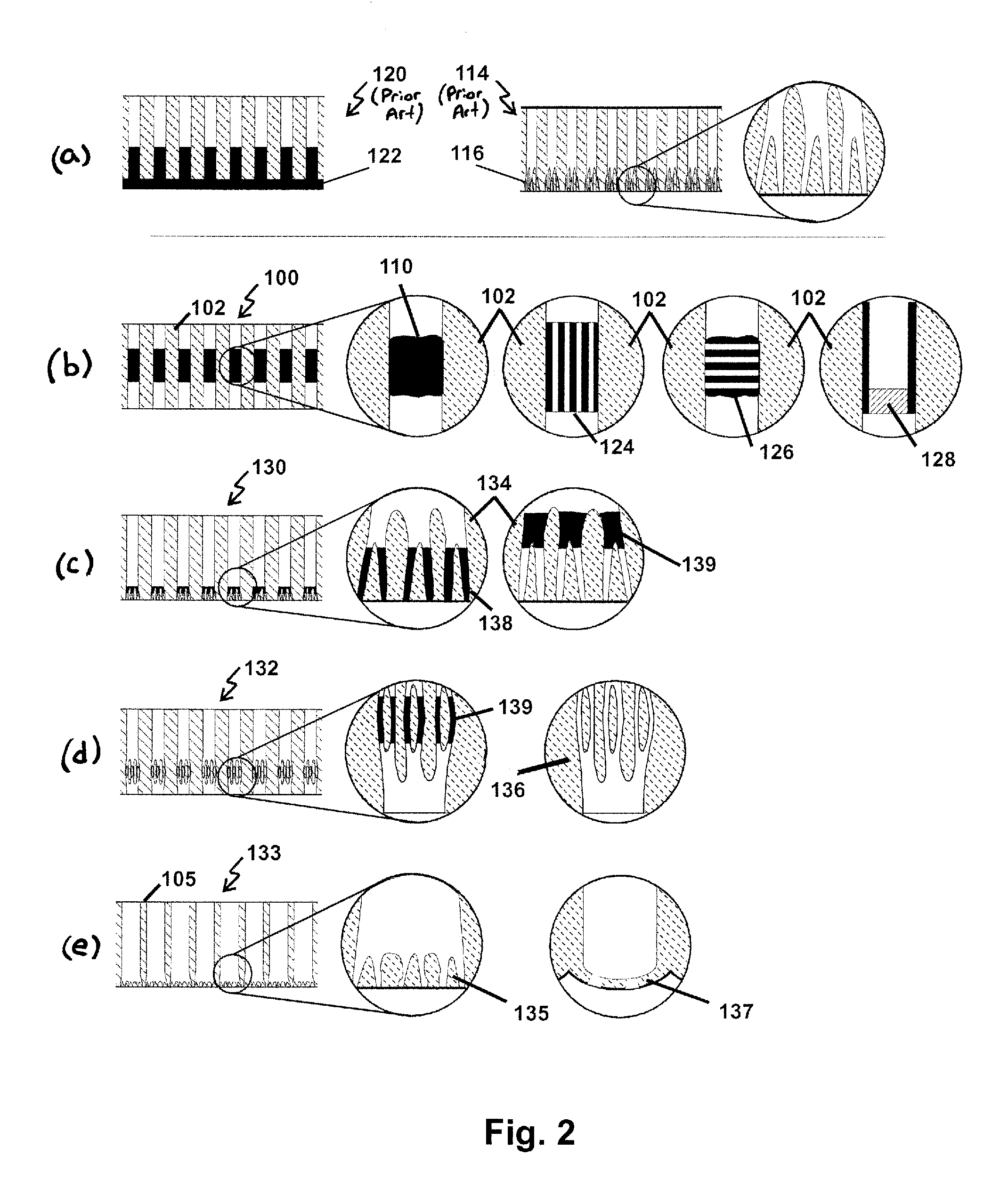
[0128]AAO structures are formed by anodizing 99.99% pure Al foil that is rolled and pressure-annealed at 350° C. and 5,000 psi for 20 min. The resulting Al foil is cleaned and anodized on both sides in 1% oxalic acid electrolyte at a temperature of 10° C. and an anodization current density of 10 mA / cm2, until a charge density of 20 C / cm2 is accumulated. The resulting layer of aluminum oxide is then etched out using a hot solution of 200 g / l chromic oxide in 50% phosphoric acid, the Al substrate is rinsed and dried, and an adhesion layer of 0.5 μm of AAO is grown using the same conditions.

[0129]Conventional photoresist is applied to both sides of the Al substrate, is soft-baked at 90° C. for 20 min and is exposed to a UV light using a mask with the openings of required size and format to define the number, the location, the size and the format of the membranes—in this case, four 25 mm circular membranes on each side of a 70 mm×70 mm substrate. Fin...

Example

Example 2

AAO Structure with Large Pore Period and Pore Diameter

[0132]Al substrates are prepared as noted in Example 1, except that after forming an adhesion layer of 0.5 μm of porous AAO and applying photoresist mask, the adhesion layer in the exposed area is etched out using a hot solution of 200 g / l chromic oxide in 50% phosphoric acid, the Al substrate is rinsed and the substrate is placed in a non-pore-forming electrolyte (0.1 M boric acid), to form a dense layer of alumina at a voltage equal or lower than the final anodization voltage, but no less that 25% of the final anodization voltage. This dense layer is required to achieve the final anodization voltage rapidly in the beginning of the final anodization step, and ensures the creation if the required pore period throughout the entire AAO structure.

[0133]Final anodization is carried out in a high voltage electrolyte (1% oxalic acid with one of the additives listed in Table 1) at a temperature of 0° C. to 2° C. and an anodizat...

Example

Example 3

AAO Membranes with an Al Rim

[0134]AAO support structures are produced using Al foil prepared and patterned as described in Example 1, except only one side of the Al substrate is anodized. Anodization is carried out in 3% oxalic acid electrolyte at a temperature of 12° C. and an anodization voltage of 40V until a charge density of 200 C / cm2 is accumulated, resulting in 100 μm thick AAO structures with 37 nm pores. With some Al substrates, voltage reduction profile #2 (FIG. 6(a)) is used to bring the anodization voltage down to 4 V, and anodization is continued for 100 seconds at 4V. The resulting asymmetric AAO structure has a final pore channel diameter of about 5 nm.

[0135]The resulting AAO structures, which are still attached to Al, are masked with 3M electroplating tape to define 8 mm circles in the center of the 13 mm structures. The barrier layer in the exposed area is breached in a solution of concentrated hydrochloric acid at −2° C. by slow ramping of the cathodic pot...


PUM

PropertyMeasurementUnit
Pore sizeaaaaaaaaaa
Pore sizeaaaaaaaaaa
Pore sizeaaaaaaaaaa

Abstract

Membranes including anodic aluminum oxide structures that are adapted for separation, purification, filtration, analysis, reaction and sensing. The membranes can include a porous anodic aluminum oxide (AAO) structure having pore channels extending through the AAO structure. The membrane may also include an active layer, such as one including an active layer material and/or active layer pore channels. The active layer is intimately integrated within the AAO structure, thus enabling great robustness, reliability, resistance to mechanical stress and thermal cycling, and high selectivity. Methods for the fabrication of anodic aluminum oxide structures and membranes are also provided.

Description

CROSS-REFERENCE TO RELATED APPLICATIONS[0001]This application claims priority as a continuation-in-part application to U.S. patent application Ser. No. 11 / 745,449 filed May 7, 2007, which claims priority to U.S. Provisional Patent Application Ser. No. 60 / 767,513, filed on May 7, 2006. Each of the foregoing U.S. patent applications is incorporated herein by reference in its entirety.STATEMENT REGARDING FEDERALLY-FUNDED RESEARCH[0002]This invention was funded in part by the National Science Foundation under Grant Nos. 0420147, 0548757, 0539824 and 0724478, and by the Department of Energy under Grant No. DE-FG02-04ER84086, each administered by the Small Business Innovation Research (SBIR) program. The Government has certain rights in this invention.BACKGROUND OF THE INVENTION[0003]1. Field of the Invention[0004]The present invention relates to methods for making membranes based on anodic aluminum oxide (AAO) structures and applications of the membranes. The membranes may include two or...

Claims


Application Information

Patent Timeline
IPC IPC(8): C25D11/12C25D11/08C25D11/06C25D5/48
CPCB01D53/228B01D67/0065B01D69/10B01D2323/18B01D2325/021B01D2325/06C01B2203/1223C01B3/503C01B2203/0233C01B2203/0405C01B2203/041C01B2203/0465C01B3/323
Inventor ROUTKEVITCH, DMITRIPOLYAKOV, OLEG G.
Owner INTEGRATED DEVICE TECH INC
Why Eureka
Try Eureka