Apparatus & method for ion beam implantation using scanning and spot beams with improved high dose beam quality

a scanning and spot beam technology, applied in the field of apparatuses and methods of ion implantation, can solve the problems of large perveance beam blowing, severe limit of beam current to a target, and the prior art ion implanter technology cannot meet these requirements, so as to improve dose uniformity, high current implantation, and reduce production cost

Active Publication Date: 2010-09-23
KINGSTONE SEMICONDUCTOR LIMITED COMPANY
View PDF2 Cites 14 Cited by
  • Summary
  • Abstract
  • Description
  • Claims
  • Application Information

AI Technical Summary

Benefits of technology

[0012]It is an aspect of the present invention to provide a new and improved beam scanning system for carrying out the ion implant operation with a high current implantation with improved dose uniformity without sacrificing the implantation angle uniformity while reducing the production cost and simplifying the manufacturing processes.
[0013]Specifically, it is an aspect of the present invention to provide a new and improved beam scanning system for carrying out the ion implant operation with the ion beams magnetically scanned in a non-dispersive plane so that the unnecessary beamline components can be eliminated. The beam scan operation can be carried out with a short beamline and higher beam currents transported in a low energy.
[0014]It is a further aspect of the present invention to provide a new and improved beam scanning system for carrying out the ion implant operation with flexibility to fine tune the implant angle by fine tuning Panofky coil currents. Since the beam can be flexibly controlled to transmit to different positions, the current on the Panofky coil can be adjusted to fine tune the beam incident angle based on the required beam implant angles. Precise control of the implant angles can be more conveniently and more accurately achieved.
[0015]It is a further aspect of the present invention to provide a new and improved beam scanning system for carrying out the ion implant operation with improved implant dose uniformity. The dose uniformity can be more conveniently achieved by, first measuring the beam currents at different scan positions; second, decide scan velocity profile based on measured beam currents along the scan positions; third, implant the target at this scan velocity profile. Therefore, precise control of the implant dose uniformity can be more conveniently and more accurately achieved.
[0016]It is a further aspect of the present invention to provide a new and improved beam scanning system for carrying out the ion implant operation with improved beam utilization by applying a beam scanning system to perform the beam scanning operation with a beam controllable to have a high speed and quick turnaround operation.

Problems solved by technology

However, prior arts ion implanter technologies cannot meet these requirements.
The large Perveance beam tends to be blowup during its transportation.
Any electrostatic potential exists in the beamline that is for ion beam generation and transportation can severely limit beam currents to a target.
The major issue of this approach in generating and employing a ribbon beam is that the ribbon beam cannot be generated with uniform implant angle and also provide uniform implant dose.
In this approach the major problem is that beamline needs a lot of magnetic lens in order to make beam shape is proper for its magnetic scanning to work.
Therefore, the beamline is very long for a beam's transportation.
Also, mechanical turnaround in reciprocal motion can result a lot implant dead time.
Therefore, this beam scanning process has very poor ion beam utilization and low productivities thus causing higher production costs and unnecessary wastes of energy and manufacturing resources.

Method used


Image

  • Apparatus & method for ion beam implantation using scanning and spot beams with improved high dose beam quality
  • Apparatus & method for ion beam implantation using scanning and spot beams with improved high dose beam quality
  • Apparatus & method for ion beam implantation using scanning and spot beams with improved high dose beam quality

Examples


Embodiment Construction

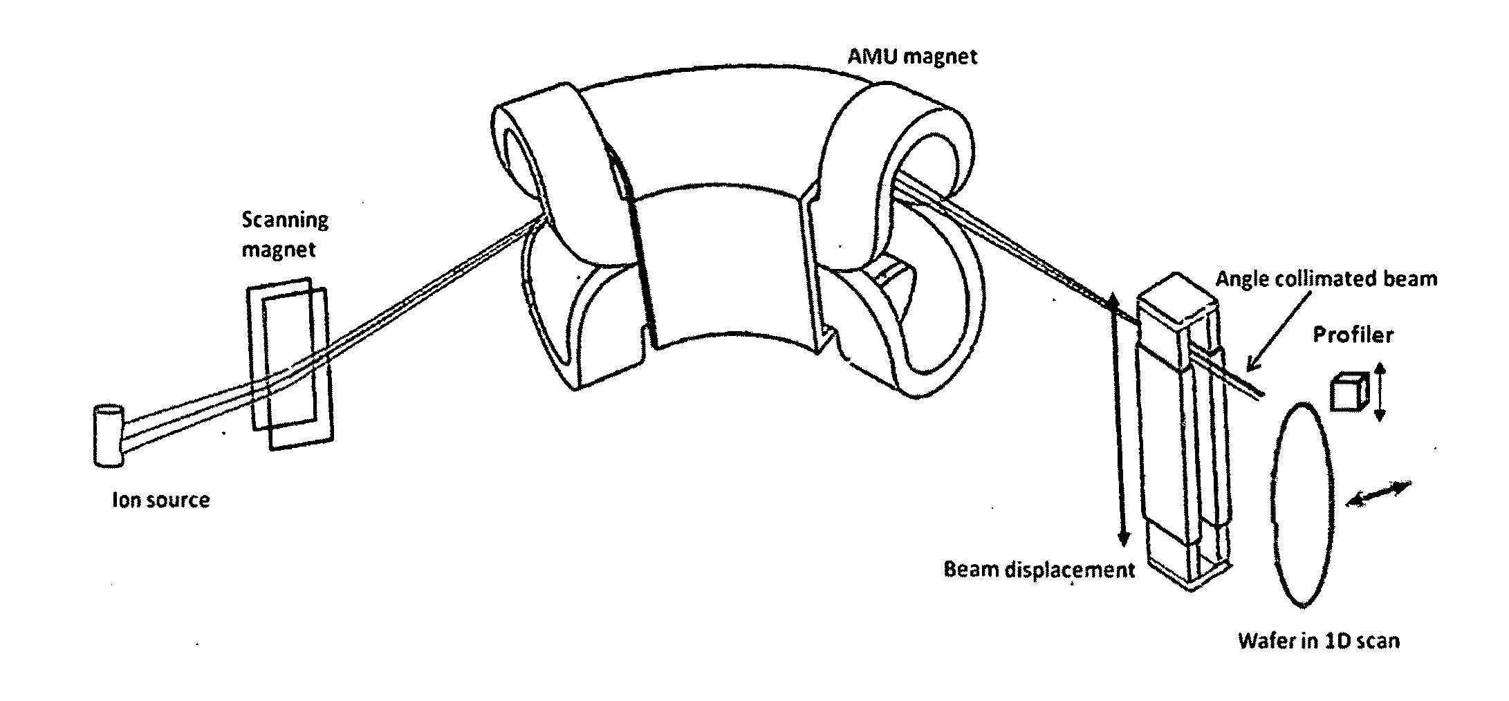
[0026]FIG. 5 is a perspective view of a first embodiment of an ion implantation system of the present invention. The system comprises an ion source that produces an ion beam that emanates from a divergent extraction optics, a scan magnet, a mass analyzer magnet, and a rectangular quadrupole magnet. The scan mechanism is before the AMU magnet. A Small scan angle range can get large beam displacement. As will be appreciated by those skilled in the art, these elements are housed in a vacuum enclosure (not shown). The mass analyzer magnet is large pole-gap window-frame dipole. The details of the analyzer magnet are described in U.S. Pat. Nos. 5,736,743 and 6,403,967 and the disclosures made in these patents are hereby incorporated by reference in this patent application. The scan magnet scans the beam by controlling the scan magnet coil current. The beam is scanned slower where a measurement of beam current is smaller and faster where the beam current is higher. By applying such control...


PUM


Abstract

An ion implantation apparatus with multiple operating modes is disclosed. The ion implantation apparatus has an ion source and an ion extraction means for forming a converging beam on AMU-non-dispersive plane therefrom. The ion implantation apparatus includes magnetic scanner prior to a magnetic analyzer for scanning the beam on the non-dispersive plane, the magnetic analyzer for selecting ions with specific mass-to-charge ratio to pass through a mass slit to project onto a substrate. A rectangular quadruple magnet is provided to collimate the scanned ion beam and fine corrections of the beam incident angles onto a target. A deceleration or acceleration system incorporating energy filtering is at downstream of the beam collimator. A two-dimensional mechanical scanning system for scanning the target is disclosed, in which a beam diagnostic means is built in.

Description

[0001]The Non-Provisional Application claims a Priority Date of Mar. 18, 2009 benefited from a Provisional Application 61 / 210,447 filed by a same Applicant of this Non-Provisional Application. The disclosures made in Provisional Application 61 / 210,447 are hereby incorporated by reference in this Non-Provisional Application.FIELD OF THE INVENTION[0002]The invention relates generally to apparatuses and methods of ion implantation. More particularly, this invention relates to improvements of ion implantation controls in ion beam incident angles, dose accuracy, implantation apparatus productivities at a wide range of ion energies from few hundreds of eV to several tens of keV and further improving the high dose implant qualities of the scan beams.BACKGROUND OF THE INVENTION[0003]High dose ion implants require high ion beam currents in order to maintain high implanter productivity. In the advanced technology integrated circuit fabrications, very low energy and high beam current implants ...

Claims


Application Information

Patent Timeline
Patent Type & Authority Applications(United States)
IPC IPC(8): H01J37/317H01J49/26H01J37/147
CPCH01J37/3171H01J49/00H01J2237/057H01J2237/1526H01J2237/30472H01J2237/166H01J2237/24528H01J2237/24542H01J2237/153
Inventor CHEN, JIONG
Owner KINGSTONE SEMICONDUCTOR LIMITED COMPANY
Why Eureka
Try Eureka