
Structural Components for Oil, Gas, Exploration, Refining and Petrochemical Applications

a technology of structural components and oil, which is applied in the direction of metal rolling stands, pipe protection against corrosion/incrustation, synthetic resin layered products, etc., can solve the problems of corroding fluids, corroding equipment with high organic acid content, and corrosion of metallic surfaces

Active Publication Date: 2010-10-21
CHEVROU USA INC
View PDF65 Cites 24 Cited by
  • Summary
  • Abstract
  • Description
  • Claims
  • Application Information

AI Technical Summary

Benefits of technology

[0160]This written description uses examples to disclose the invention, including the best mode, and also to enable any person skilled in the art to make and use the invention. The patentable scope is defined by the claims, and may include other examples that occur to those skilled in the art. Such other examples are intended to be within the scope of the claims if they have structural elements that do not differ from the literal language of the claims, or if they include equivalent structural elements with insubstantial differences from the literal languages of the claims. All citations referred herein are expressly incorporated herein by reference.

Problems solved by technology

Aqueous fluids, such as those used in drilling and completion, can contribute salts, amines, acids, or other contaminants, causing the fluids to be corrosive.
Crudes with high organic acid content such as those containing naphthenic acids are corrosive to the equipment used to extract, transport, and process the oil.
Degradation of the absorbent and acidic components, as well as the generation of by-products, results in corrosion of metallic surfaces.
Besides the corrosion issue, there is a risk of leakage and associated fire protection and fire resistant issues in the handling of petroleum products.
A loss of containment in any portion of the piping system may result in a high temperature, high heat flux, high velocity flame, frequently termed a “jet fire.” When there is a jet fire, extreme heat flux densities may occur together with high temperatures, depending on the nature of the fire.
Each approach has risks and drawbacks.
It is often not possible to monitor and plan an economic replacement schedule for equipment with a high degree of certainty.
The use of inhibitors can have unintended side effects, such as moving the corrosion to other parts of the process or possibly posing some environmental concerns.
When the cause of the corrosion is not known with certainty, or the causes of corrosion are numerous, or the corrosion varies with process changes, the selection of a resistant material is difficult and almost always very expensive.
However, lined metal pipe systems can fail due to the differences in the physical properties of the liner and the metal pipe (e.g., viscoelastic properties due to thermal cycling).
However, when structural components comprising nonmetallic composite materials are heated to their ignition or combustion support temperatures by heat transfer from a near-by flame, the materials ignite and / or support combustion, lose structural integrity, and evolve large quantities of smoke while burning.

Method used


Image

  • Structural Components for Oil, Gas, Exploration, Refining and Petrochemical Applications
  • Structural Components for Oil, Gas, Exploration, Refining and Petrochemical Applications
  • Structural Components for Oil, Gas, Exploration, Refining and Petrochemical Applications

Examples


examples

[0155]The following illustrative examples are intended to be non-limiting.

[0156]Embodiments of structural components, e.g., pipes, were modeled using finite element analysis (FEA) or predictive models. The predictive model used was a general purpose professional package from Solidworks. The modeled pipes are 8″ ID pipes, comprising glass reinforced epoxy thermoset for the structural composite layer, thermoplastics materials for the corrosion resistant layer, and a fire resistive layer comprising calcium silicate. In the thermal modeling, the corrosion resistant layer is not taken into account as the thermal data is insignificant compared to the thermal data of the structural layer and the fire resistive layer.

[0157]In example 1, the 8″ ID pipe has a structural layer with a thickness of 0.43″ and a fire resistive layer comprising calcium silicate of 2″ thick. FIG. 11 depicts the temperature of the inside of the pipe (ID) as a function of time with a forced temperature of about 1100° ...


PUM

PropertyMeasurementUnit
Temperatureaaaaaaaaaa
Fractionaaaaaaaaaa
Poweraaaaaaaaaa

Abstract

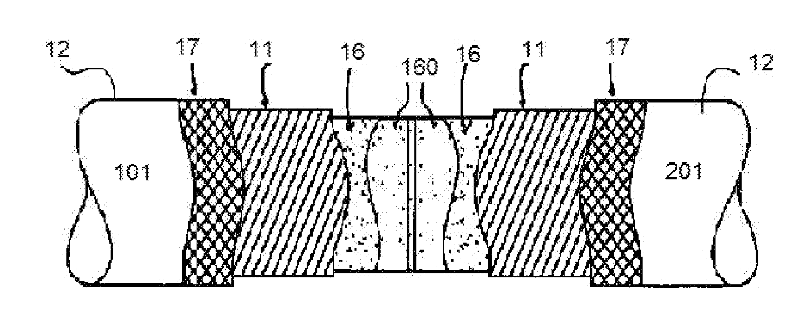
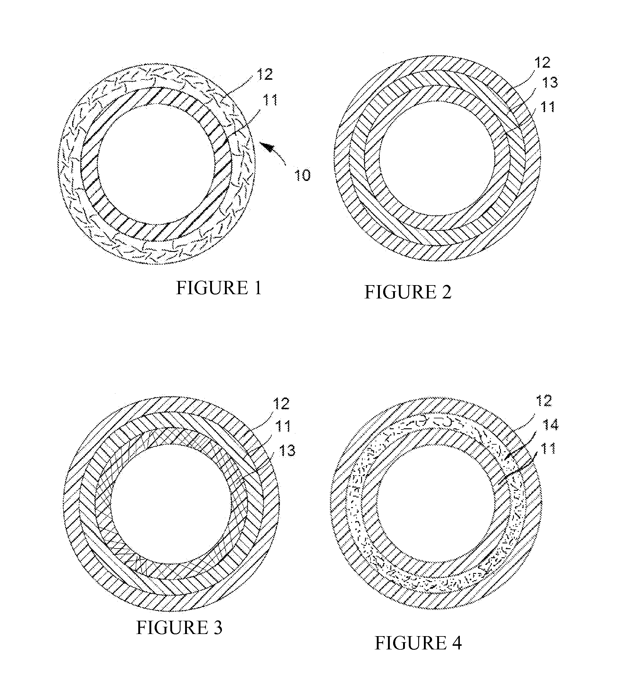
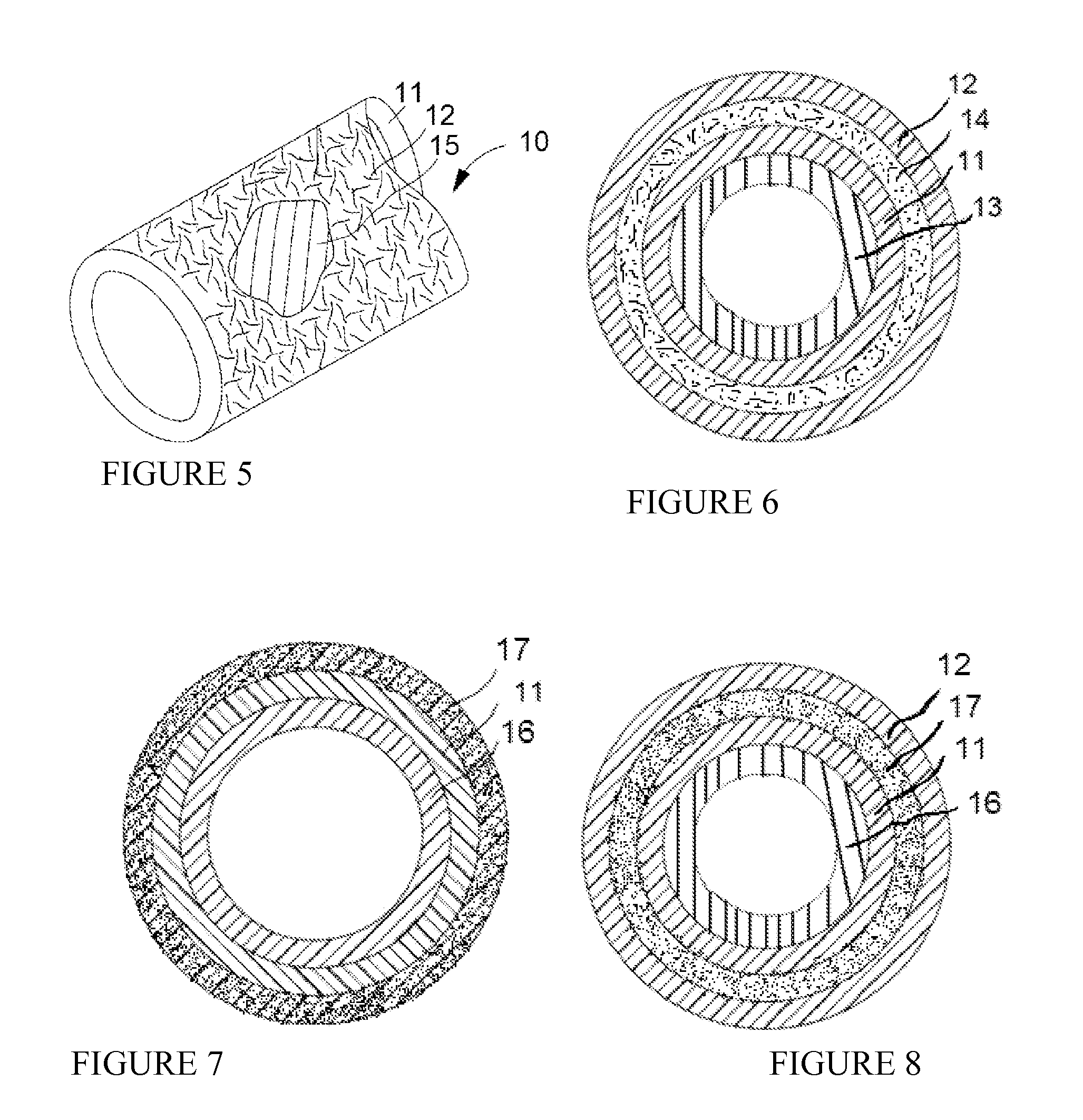
A method to form a pipe system which meets level II fire endurance standard according to IMO A 18 / Res.753 fire testing protocol, for use in oil, gas, exploration, refining and petrochemical applications is provided. In the pipe system, each pipe section comprises a plurality of layers, an inner layer in contact with the corrosive petroleum product comprising a thermoplastic material, a structural layer comprising a composite material, and an outer layer comprising a fire resistive material. The method comprises applying energy to join the corrosion resistant layers of the separate pipe sections together forming a joint, applying an external wrap around the joint and at least a portion of the composite structural layers of the at least two pipe sections, and bonding the external wrap to the joint and the composite structural layers by chemical curing, thermal treatment, or combinations thereof.

Description

CROSS-REFERENCE TO RELATED APPLICATIONS[0001]This application claims benefit under 35 USC 119 of U.S. Provisional Patent Application No. 61 / 170,080 with a filing date of Apr. 16, 2009. This application claims priority to and benefits from the foregoing, the disclosure of which is incorporated herein by reference.TECHNICAL FIELD[0002]The invention relates generally to the use of advanced materials, e.g., composites, cermet linings, amorphous metals, corrosion resistant materials, thermal resistant coatings, etc., in oil and gas exploration, refining and petrochemical applications.BACKGROUND[0003]It is known that petroleum products, i.e., gas and liquid hydrocarbon products, contain or have associated with them corrosive materials such as carbon dioxide, hydrogen sulfide, and chlorides, etc. Aqueous fluids, such as those used in drilling and completion, can contribute salts, amines, acids, or other contaminants, causing the fluids to be corrosive. Crudes with high organic acid content...

Claims


Application Information

Patent Timeline
IPC IPC(8): B23P17/00
CPCB32B1/08B32B37/00C04B35/16C04B35/6263C04B2235/349Y10T428/12493F16L58/181Y10T29/4998Y10T428/13Y10T428/26F16L57/04B32B5/022B32B5/024B32B5/026B32B5/06B32B5/147B32B5/22B32B5/24B32B5/26B32B7/12B32B9/005B32B9/04B32B9/041B32B9/045B32B9/047B32B15/04B32B15/08B32B15/14B32B15/18B32B15/20B32B27/06B32B27/08B32B27/12B32B27/18B32B27/28B32B27/283B32B27/286B32B27/304B32B27/32B32B27/322B32B27/36B32B27/38B32B27/42B32B3/266B32B2255/00B32B2255/02B32B2255/06B32B2255/10B32B2255/20B32B2255/205B32B2255/26B32B2255/28B32B2260/021B32B2260/04B32B2260/046B32B2262/02B32B2262/0261B32B2262/0269B32B2262/0276B32B2262/10B32B2262/101B32B2262/103B32B2262/105B32B2262/106B32B2264/101B32B2264/107B32B2264/108B32B2270/00B32B2307/202B32B2307/30B32B2307/304B32B2307/3065B32B2307/51B32B2307/536B32B2307/542B32B2307/546B32B2307/554B32B2307/558B32B2307/714B32B2307/7246B32B2597/00Y10T428/31529Y10T428/31678Y10T428/31663Y10T428/1317Y10T29/49732
Inventor NICCOLLS, EDWIN H.O'CONNOR, ANDREWKUSINSKI, GRZEGORZ JAN
Owner CHEVROU USA INC
Learn More