

Sound-absorbing, resistant panels and process for making same
- Summary
- Abstract
- Description
- Claims
- Application Information
AI Technical Summary
Benefits of technology
Problems solved by technology
Method used
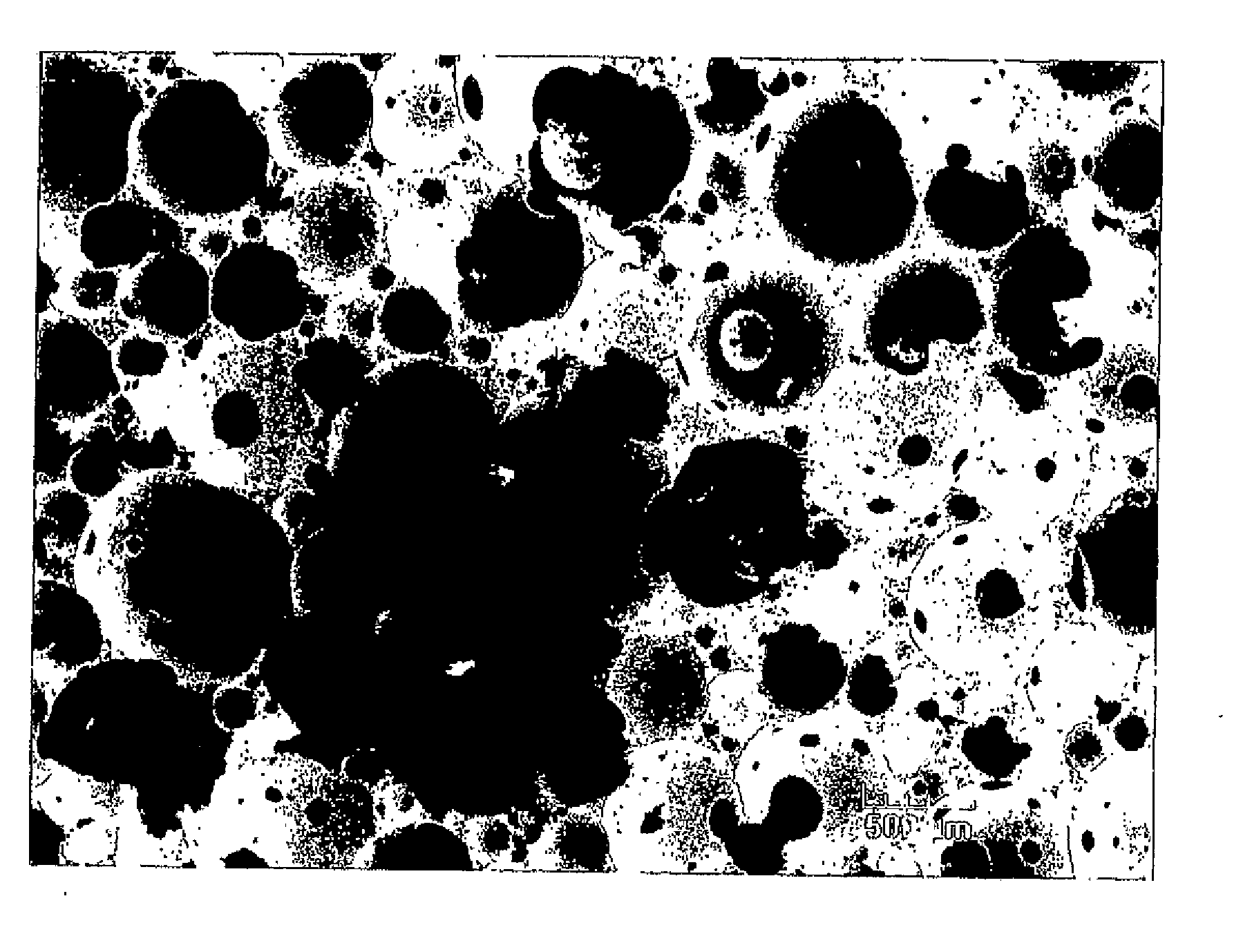
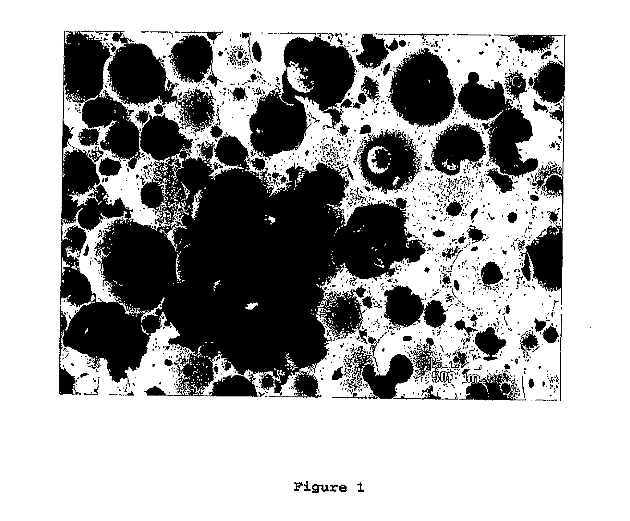
Image

Examples
example 1
Production of Panels According to the First Embodiment of the Process
[0173]In a stirred tank (primary mixer), a slurry was prepared using the following ingredients:[0174]15 g of Ball milled accelerator (BMA, from the Carpentras factory, France) which comprises 50% gypsum, 40% starch and 10% calcium lignosulfonate;[0175]This BMA is prepared by co-grinding and the particle size distribution is D10=3+ / −1 μm, D50=15+ / −3 μm and D90=60+ / −5 μm;[0176]9.45 kg of water;[0177]24 g of Coatex TP169 (polyacrylate blocking agent, obtained from Coatex);[0178]15 g of Ball milled accelerator (BMA, from the Ottmarsheim factory, France) which comprises gypsum, starch and lignosulfonate;[0179]35.7 g of Optima 100 (phosphonate fluidizer obtained from Chryso);[0180]363 g of Vinnapas CEF52W (vinyl acetate resin obtained from Wacker).
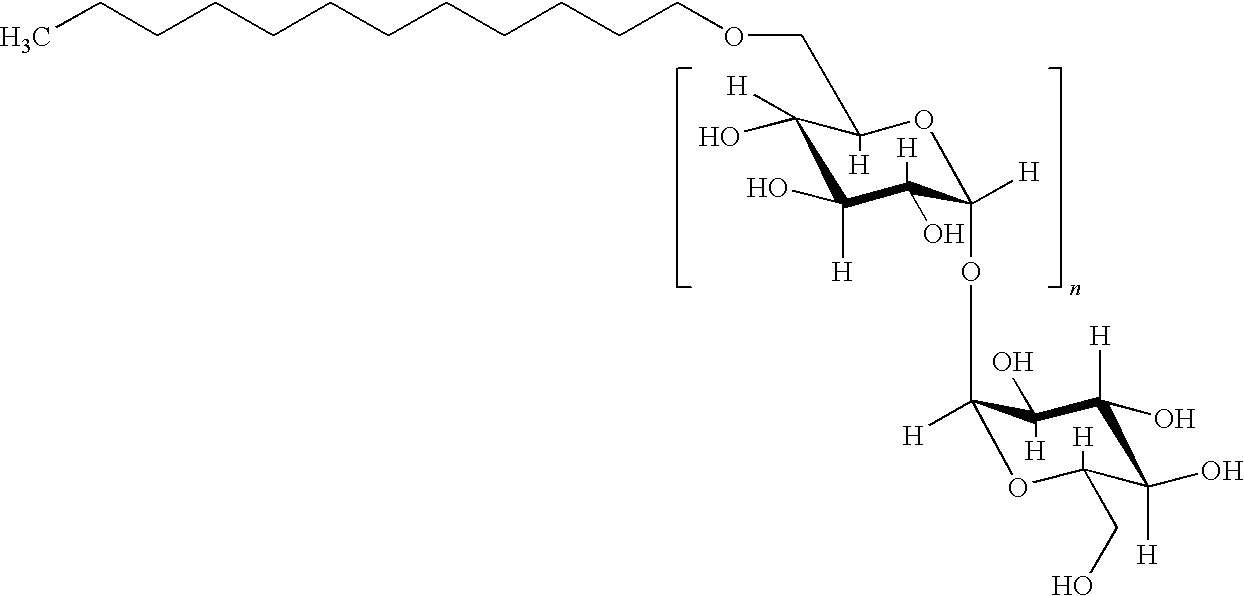
[0181]The primary slurry thus obtained was pumped in a tube at a flow rate of 1 L / min. A solution of Glucopon 215 CS UP (containing 64% by weight of alkylpolyglycoside surfacta...
example 2
Production of Panels According to the Second Embodiment of the Process
[0185]In a primary mixer, a powder premix was continuously introduced at a flow rate of 1 kg / min. The powder premix was composed of:[0186]gypsum hemi-hydrate from the Ottmarsheim factory (France) so that the water to plaster ratio is 0.58; and[0187]1 g Ball milled accelerator (BMA, see above) per kg of gypsum hemihydrate.
[0188]The following liquid ingredients were also introduced into the mixer:[0189]410 g / min of water;[0190]57 g / min of a solution of sodium polyacrylate (Coatex TP1431EXP: fluidizing agent obtained from Coatex), the solution being a 1 / 10th dilution of the commercial solution, so that the weight concentration in active material is 0.3% relative to the gypsum hemihydrate;[0191]50 g / min of a blend of natural product with proteins in solution (Plastretard L: retarder supplied by Sicit, Vincenza Chiampo, Italy) containing 6 g per kg of the initial commercial solution;[0192]50 g / min of a solution of K2SO...
example 3
Analytical Tests
[0199]Samples of the foamed slurry produced according to examples 1 and 2 were taken at the outlet of the last mixer (i.e. the secondary mixer in the continuous process and the tertiary mixer in the semi-batch process).
[0200]Some samples were placed in a 20-mm high and 75-mm wide cup where they were allowed to set. These samples were used for the analysis of mechanical performances (compression test). However, it is also possible to make the analysis directly on the boards. Force-displacement curves were plotted and the strength before breaking was measured and converted to a corresponding pressure in MPa.
[0201]Other samples were placed in a 100-mm high and 45-mm wide cup where they were allowed to set. 2-cm high slices were subsequently extracted and used for the analysis of the acoustic performances of the gypsum core. Acoustics was evaluated by Kundt tube measurements, which allow to vary the frequency of the incident waves crossing a sample perpendicularly. The n...
PUM
| Property | Measurement | Unit |
|---|---|---|
| Length | aaaaa | aaaaa |
| Length | aaaaa | aaaaa |
| Length | aaaaa | aaaaa |
Abstract
Description
Claims
Application Information