Continuous Processing Reactors and Methods of Using Same

Inactive Publication Date: 2010-11-18
R3 FUSION
View PDF2 Cites 12 Cited by
  • Summary
  • Abstract
  • Description
  • Claims
  • Application Information

AI Technical Summary

Benefits of technology

[0008]In accordance with one embodiment of the present invention, there is provided a reactor for processing fluid. The reactor includes an outer vessel having an inner surface against which a fluid being processed can be accommodated. The inner surface of the outer vessel, in an embodiment, may be designed to allow fluid being processed to descend in a substantially uniform thin film, so as to permit the fluid being processed to have a relatively high rate of thermal transfer, mass transfer, mixing, other transport rates or a combination thereof. The inner surface of the outer vessel may also be provided with a profiled pattern to create additional surface area over which the fluid being processed can flow to facilitate one of treatment, processing, separation, increase in residence time, or a combination thereof. The reactor also includes an inner vessel, situated within the outer vessel, and having an outer surface serving as a heat exchange surface for the fluid being processed. The inner vessel, in one embodiment, includes an inner surface against which a heat exchange fluid may flow. The heat exchange fluid, in general

Problems solved by technology

A common problem in chemical reaction processes is how to achieve the proper hydrodynamics in the reactor to efficiently produce the desired products.
However, over time, the coating tends to suffer from attrition and inevitably deactivate.
However, because these reactors combine high-intensity heat exchange and short time of residence of materials to be treated, such a design can cause the materials, as the materials enters the treatment chamber, to quickly expand due to a sudden temperature differential between the treatment chamber and the source, resulting in an uneven spread of the material onto the inner wall of the treatment chamber.
However, the direct contact of the wipers on the treatment surface can result in contamination of the material, as well as undesirable wear on the wipers and the inner wall of the reactor.
Moreover, beca

Method used


Image

  • Continuous Processing Reactors and Methods of Using Same
  • Continuous Processing Reactors and Methods of Using Same
  • Continuous Processing Reactors and Methods of Using Same

Examples


Example

EXAMPLE 1

Fluid-Fluid or Solid-Fluid-Fluid Reactions

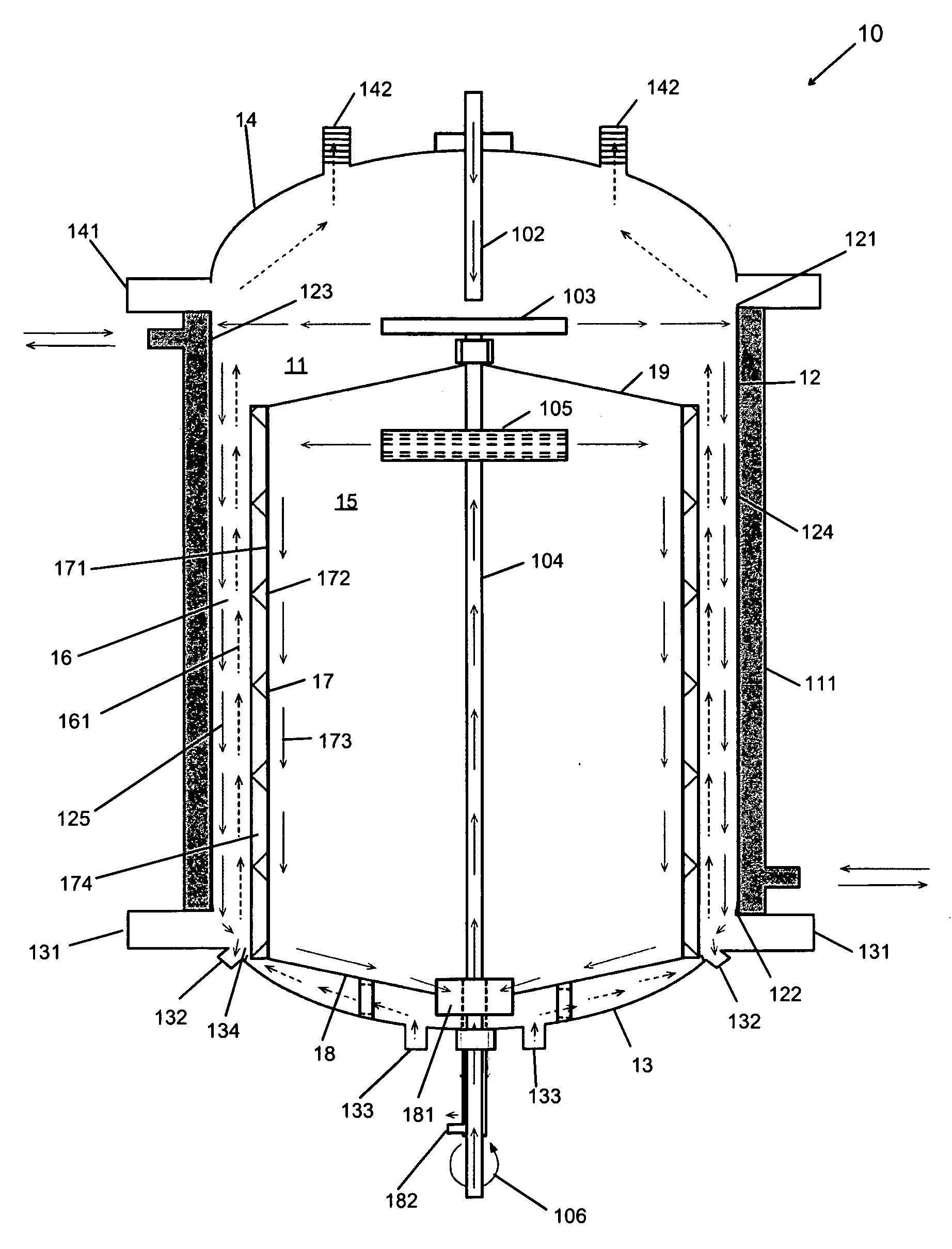
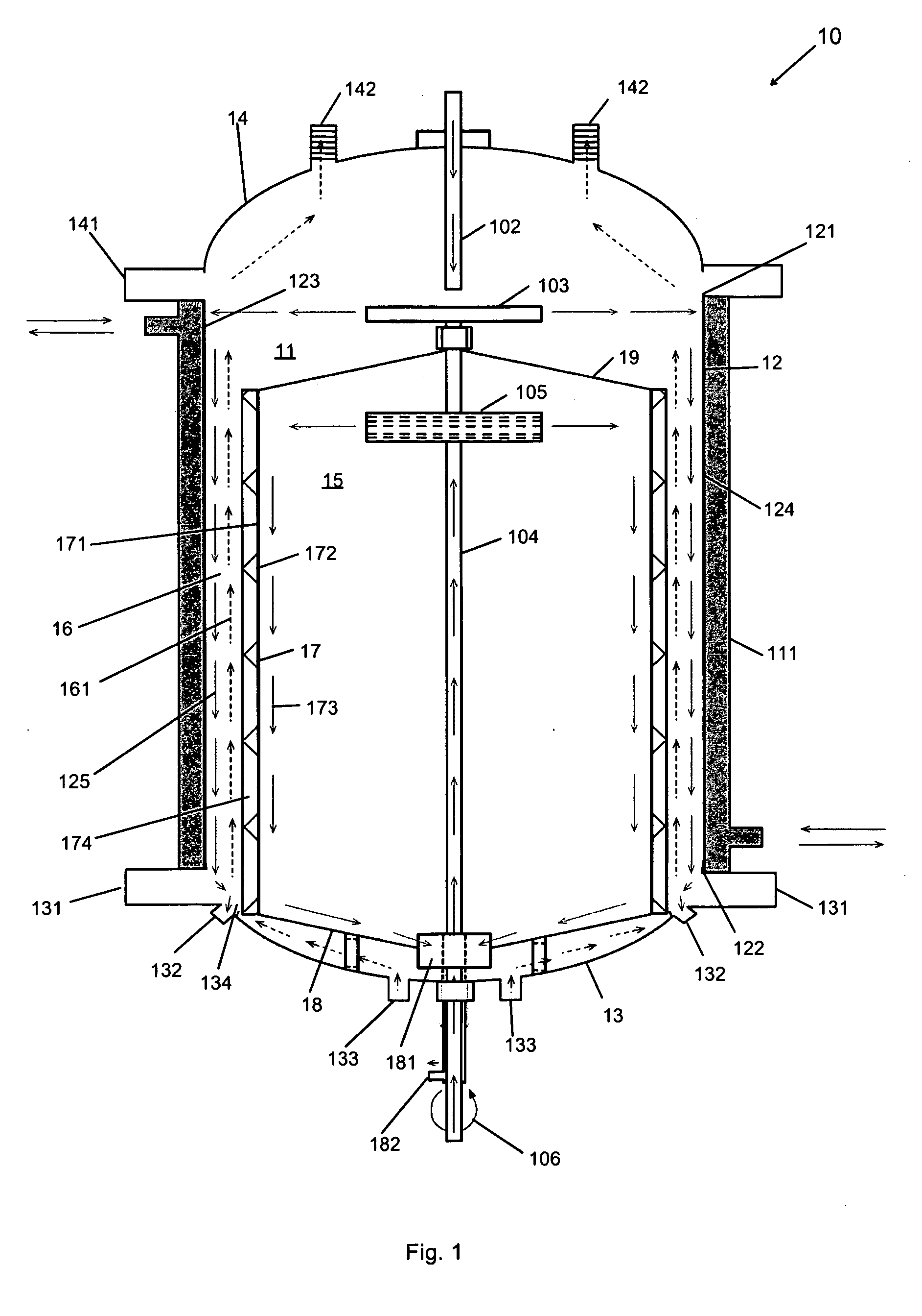
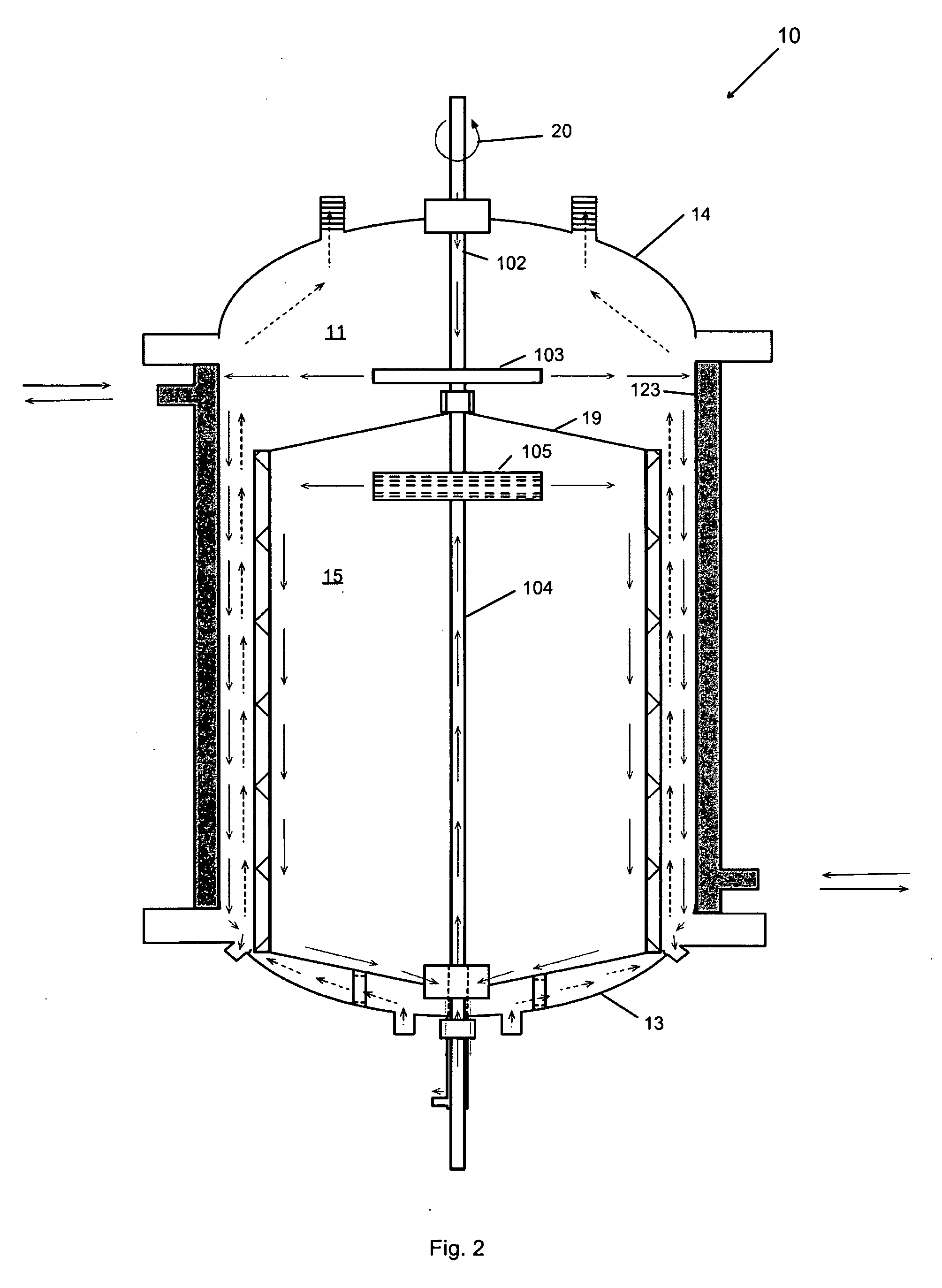
[0060]As shown in the embodiments depicted in FIGS. 1, 2, 3 and 5 the reactor 10 of the present may be applicable for fluid-fluid or solid-fluid-fluid reactions in connection with organic systems. It should be appreciated that the term fluid as used herein and throughout this application includes, gas and liquid. Thus, reactor 10 may be applicable, for example, for gas-liquid, liquid-liquid, solid-gas-liquid reactions, or any other combination.

[0061]The reactor 10 illustrated in FIGS. 1, 2, and 3, in one embodiment, has particular application for organic systems where higher pressures and temperatures are used, for instance, hydrogenation, oxidation, polymerization, dealkylation, alkylation, methylation, carboxylation, decarboxylation, and Fisher-Tropps, among others. This application may further be useful in, for instance, the production of organic products from coal slurry or the production of dimethyl ether (DME) using either nat...

Example

EXAMPLE 2

Evaporation and Distillation

[0066]As shown in the embodiment depicted in FIG. 5, reactor 50 of the present invention may be used in evaporation and distillation processes. Evaporation and distillation processes include, for instance, removing water from oil, ethanol, methanol, glycerine, or other compounds. In addition, such processes may include removing light organics from heavy organics, such as light sweet crude from heavy oil, methanol from biodiesel and glycerine mix, methanol from glycerine, and light organics from heavy oil. Furthermore, such processes may include removing organic solvents such as ethyl acetate from polymer dispersion or removing organic solvents or monomers during depolymerization processes. It may also be used in desalination of water, concentration of fruit juice, concentration of food materials, such as soup, milk, removal of light organics from ground water, removal of dissolved organics from processed water (i.e., industrial waste water), and ...

Example

EXAMPLE 3

Deheating of Superheated Steam

[0073]In the embodiment depicted in FIG. 6, reactor 60 of the present invention may be used in connection with cooling of superheated steam, or desuperheating of steam. Both the inner surface 123 of outer vessel 11 and outer surface 171 of inner vessel 15 may be maintained at a temperature measurably lower (i.e., cooler) relative to the superheated steam.

[0074]To maintain the inner surface 123 of outer vessel 11 at a relatively cool temperature, a relatively cool liquid may be introduced through pathway 102 distributed by the first rotatable member 103 on to and substantially uniformly along the inner surface 123 of outer vessel 11. In addition or alternatively, jacket 111 may be set at a predetermined temperature level to keep the inner surface 123 at such a relatively cool temperature. To maintain the outer surface 171 of the inner vessel 15 at a similar relatively cool temperature, a relatively cool liquid may be introduced through tube 104 ...


PUM


Abstract

A system having a reactor for continuous processing of fluid is provided herein. The reactor, in general, includes an outer vessel to accommodate fluids to be processed or used in connection therewith, an inner vessel situated within the outer vessel to serve as an energy exchange surface, and an annular space defined between the outer and inner vessels and along which processing of the fluids can be implemented. The continuous thin film reactor can be used to perform, for example, distillation and evaporation, fluid-fluid or solid-fluid-fluid reactions, organic reactions, cooling, and desalination.

Description

TECHNICAL FIELD[0001]The present invention relates processing reactors, and more particularly, to continuous processing reactors that can impart fluid being processed with high heat transfer, mass transfer, mixing rates, and other high transport rates.BACKGROUND ART[0002]A common problem in chemical reaction processes is how to achieve the proper hydrodynamics in the reactor to efficiently produce the desired products. The reactants need to be mixed so that the molecules of the reaction components come into contact with the other components in the reaction including catalysts. The presence of a gaseous reactant can further require an increase in the surface area of the boundary between the gas and the liquid components to increase the efficiency of the reaction.[0003]To improve mixing and contact between the reaction components, thin film reactors have been designed to include, among other things, a coating of a catalyst to the inner surface (i.e., treatment surface) of the treatmen...

Claims


Application Information

Patent Timeline
IPC IPC(8): C02F1/08C02F1/26C02F1/469
CPCB01J4/007C02F2303/04B01J19/0066B01J19/1887B01J19/2485B01J19/2495B01J19/30B01J2219/00085B01J2219/00094B01J2219/00765B01J2219/00779C02F1/006C02F1/04C02F1/30C02F1/302C02F1/32C02F2101/30C02F2103/06C02F2103/08B01J10/02Y02A20/124
Inventor JACHUCK, ROSHAN J. J.JACHUCK, SUPRIYA
Owner R3 FUSION
Why Eureka
Try Eureka