Biomass gasification apparatus

a gasification apparatus and biomass technology, applied in the field of gasification technology, can solve the problems of inability to provide high-quality gas generation, difficult advanced energy use, and inability to provide electric power output, etc., to achieve the effect of improving gasification performance efficiency, high temperature and large volum

Active Publication Date: 2010-12-02
NAGASAKI INSTITUTE OF APPLIED SCIENCE
View PDF3 Cites 7 Cited by
  • Summary
  • Abstract
  • Description
  • Claims
  • Application Information

AI Technical Summary

Benefits of technology

[0049]According to the present invention, the heat source required to heat the primary gasification reaction room can be obtained as the combustion gas of a biomass by the high-temperature combustion gas generation apparatus. In particular, by the high-temperature combustion gas generation apparatus structured to have a three-stage air supply by a downward flow, clean combustion gas having higher temperature can be obtained.
[0050]Furthermore, the biomass supply hopper including the coarse powder-accompanying gas supply line can prevent the dew condensation in the biomass supply hopper or water absorption by the biomass in the biomass supply hopper, thus improving the gasification performance efficiency.
[0051]Furthermore, the porous plate provided in the primary gasification reaction room not only can realize the gasification processing of coarse biomass having a large particle size but also can prevent the deterioration of the quality of the generated gas.
[0052]By the biomass gasification apparatus of the present invention, clean and high-quality fuel gas can be obtained. This fuel gas has combustion temperature equal to that of fossil fuel. Thus, this fuel gas can be used for gas engine power generation and gas turbine power generation having high power generation efficiency.
[0053]Furthermore, the composition of the fuel gas includes H2 and CO as main components. Thus, the fuel gas also can be used as synthesis gas for chemically-synthesized raw material and can be used as raw material gas for the manufacture of liquid fuel such as methanol and GTL.

Problems solved by technology

In this case, advanced energy use is difficult.
Such a small-scale power generation of 100 kW cannot provide an output of electric power.
However, this process causes a large amount of soot and tar and also causes exhaust gas used for heat generation to be mixed in the generated gas, thus failing to provide generation of high-quality gas.
In the case of a method of manufacturing liquid fuel out of biomass however, both of ethanol fuel obtained by fermentation of carbohydrate and starch as raw material and BDF (bio diesel oil fuel) obtained by the esterification of vegetable oil by an addition of methanol are manufactured meinly out of food as raw material and thus provides a low yield per area under cultivation.
Due to this, disadvantages have been caused in that the generated gas is mixed with a large amount of carbon dioxide gas and nitrogen included in the high temperature complete combustion gas to cause a deteriorated quality of generated gas, generated gas and biomass as raw material of generated gas are dissipated, the distribution of gasification agent is uneven, and many fine pores must be processed for example.
Although the above disadvantages are solved by the addition of water vapor, some technical problems including the following points that should be solved or improved remain unsolved.
The first disadvantage is that biomass as gasification raw material must be fine powders of about 3 mm or less and thus a high grinding power is required and coarse powders of 10 to 20 mm cause a trouble.
The second disadvantage is that the gasification agent supplied to the gasification space (e.g., water vapor) intrudes into a biomass supply hopper to cause dew condensation or to cause the biomass fine powders to contain a large amount of water.
This consequently makes it difficult to smoothly supply the biomass fine powders to the gasification space, thus remarkably deteriorating the gasification efficiency in the gasification reaction room.
The third disadvantage is that a ratio of hydrogen in the composition of the resultant fuel gas is low and thus the resultant fuel gas is still insufficient as synthesis gas for synthesizing methanol or GTL for example.

Method used


Image

  • Biomass gasification apparatus
  • Biomass gasification apparatus
  • Biomass gasification apparatus

Examples


first embodiment

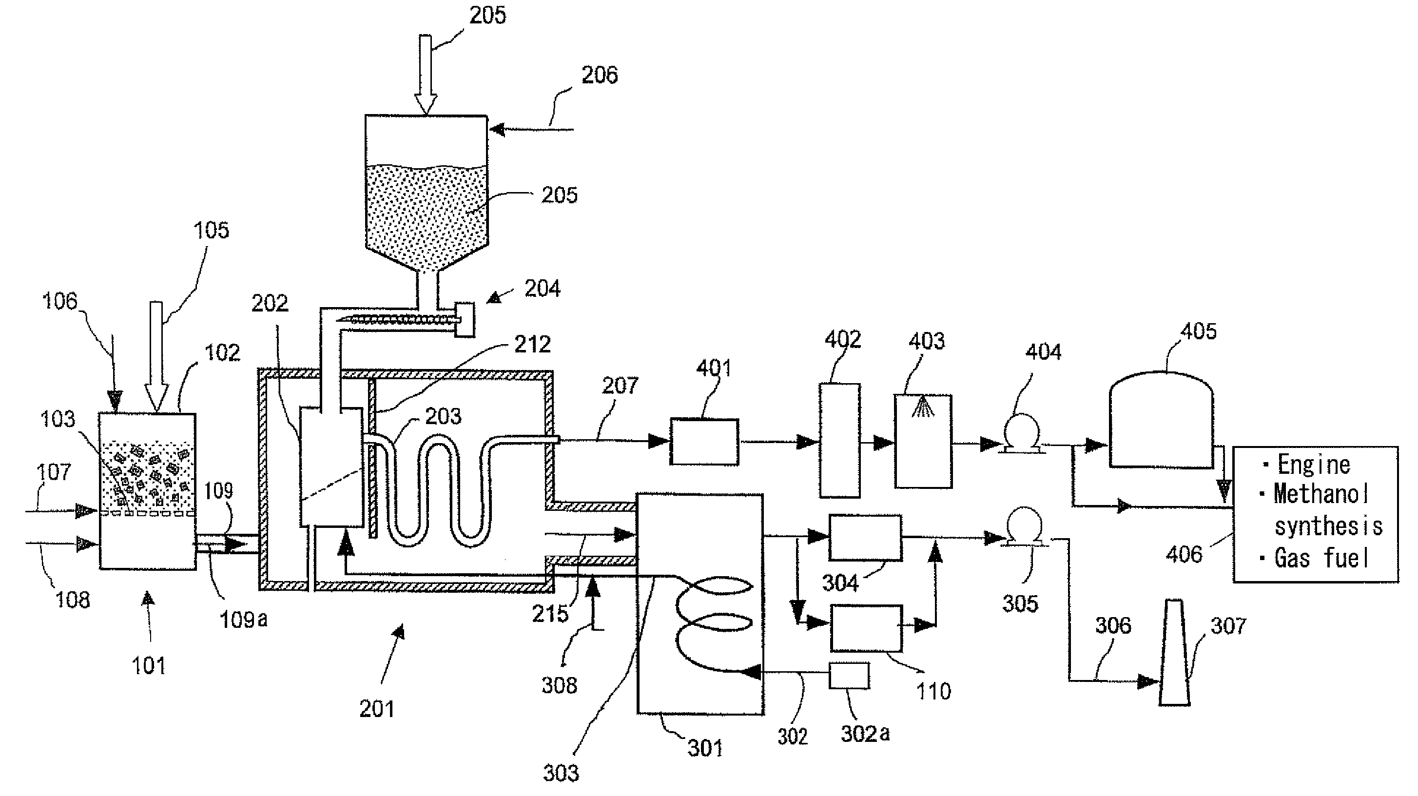
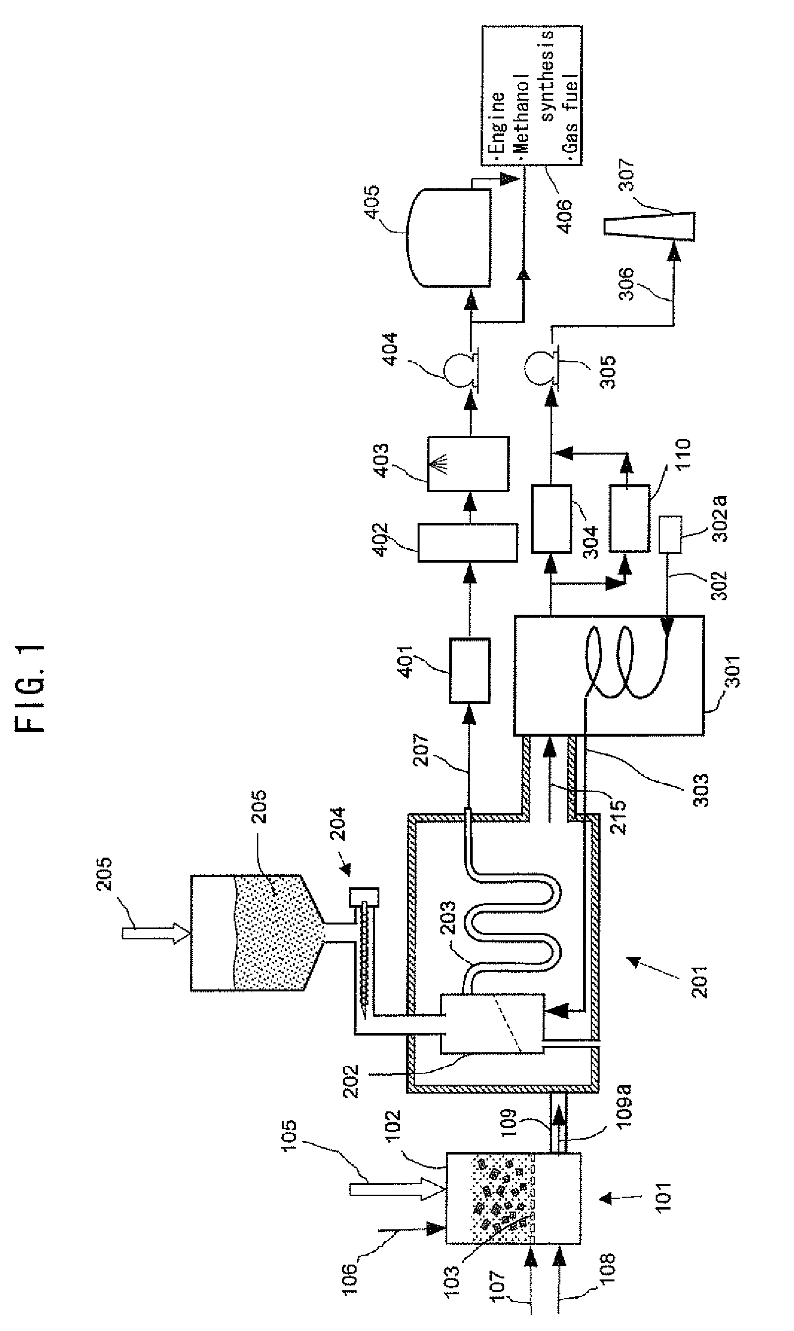
[0106]FIG. 1 illustrates one embodiment of a biomass gasification apparatus of the present invention.

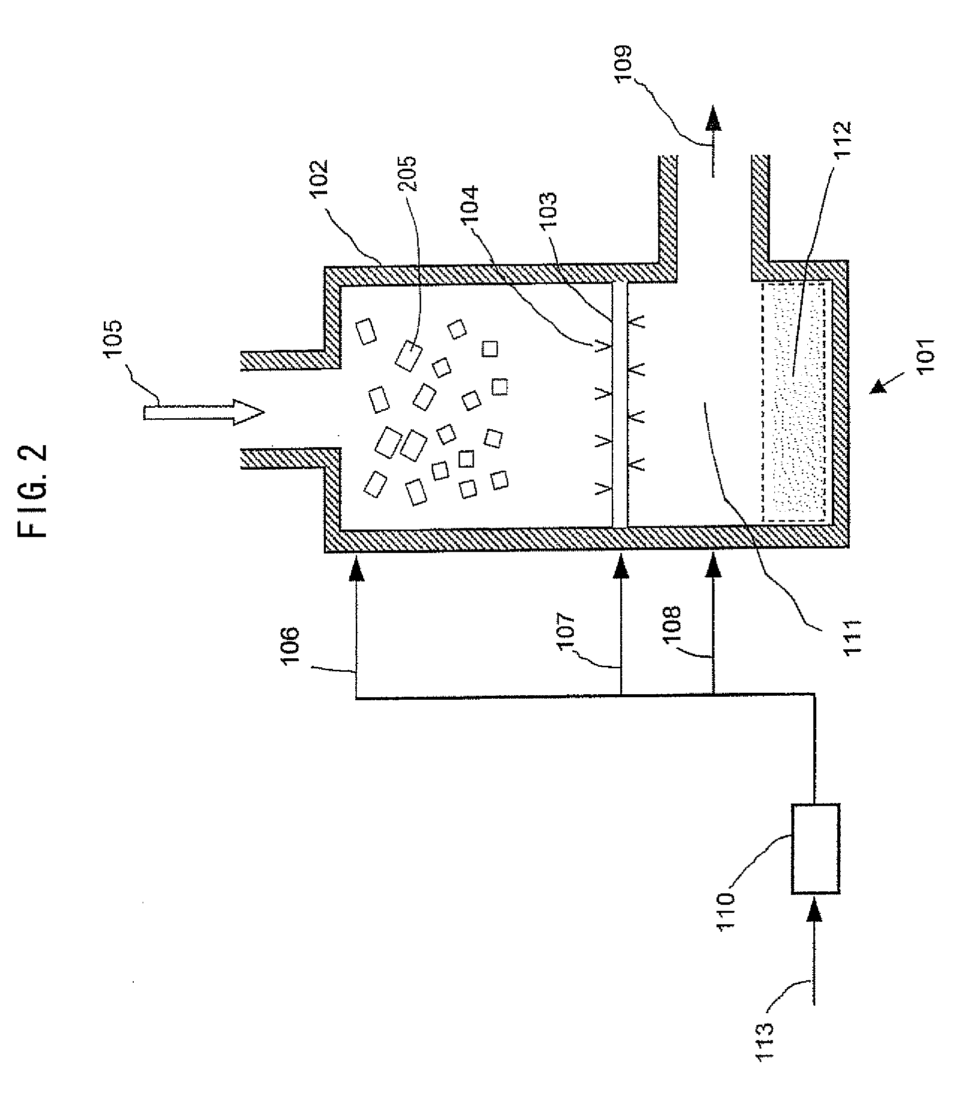
[0107]In a high-temperature combustion gas generation apparatus 101, biomass is combusted to generate clean combustion gas 109a (shown by the arrow) having high temperature exceeding 900 degrees C. The combustion gas 109a is sent from a combustion gas supply line 109 to a gasification reaction apparatus 201 to heat a primary gasification reaction room 202 provided in the gasification reaction apparatus 201 and a secondary gasification reaction pipe 203 connected to the primary gasification reaction room 202 from the outer wall face. Thereafter, the combustion gas 109a is exhausted as exhaust gas 215 from the gasification reaction apparatus 201.

[0108]The exhaust gas 215 causes overheat water vapor 303 to be generated in a waste heat boiler 301. The overheat water vapor 303 is supplied from a gasification agent supply line 302 to a bottom section of the primary gasification reaction ro...

second embodiment

[0132]FIG. 5 shows a schematic view illustrating the gasification reaction apparatus 201 according to the second embodiment of the present invention in which the biomass supply hopper 208 has a coarse powder-accompanying gas supply line 206.

[0133]In this embodiment, N2, CO2, air, or the mixture thereof as coarse powder-accompanying gas 206a is sent from the coarse powder-accompanying gas supply line 206 into the biomass supply hopper 208 for temporarily storing the coarsely-ground powder biomass chips 205. Most part of the coarse powder-accompanying gas and the biomass chip 205 are dropped and supplied to the primary gasification reaction room 202 via the biomass supply line 204.

[0134]When this coarse powder-accompanying gas 206a is not supplied, a part of the water vapor introduced in a great amount to the primary gasification reaction room 202 via the biomass supply line 204 flows into the biomass supply hopper 208. This causes, according to an experiment, the dew condensation of ...

third embodiment

[0138]FIG. 6 shows a schematic view illustrating a gasification reaction apparatus according to the third embodiment of the present invention in which a heat-resistant partition wall is further included therein.

[0139]In this embodiment, the primary gasification reaction room 202 and the secondary gasification reaction pipe 203 are divided by a heat-resistant partition wall 212 for the purpose of blocking radiation heat. The first gasification reaction room 202 forms a reaction furnace high temperature room 209 independent from the secondary gasification reaction pipe 203. The combustion gas generated in the high-temperature combustion gas generation apparatus 101 is sent to the gasification reaction apparatus 201 to firstly heat the primary gasification reaction room 202 to secondly heat the secondary gasification reaction pipe 203. Since the primary gasification reaction room 202 forms the reaction furnace high temperature room 209 independent from the secondary gasification reacti...


PUM

PropertyMeasurementUnit
power generation efficiencyaaaaaaaaaa
electric poweraaaaaaaaaa
sizeaaaaaaaaaa

Abstract

A biomass thermochemical gasification apparatus is provided that can manufacture high-quality fuel gas out of solid biomass in an industrial manner. This fuel gas can be used as fuel for a gas engine and a gas turbine for example and also can be used as synthesis gas for methanol synthesis.A high-temperature combustion gas generation apparatus (101) for biomass operates entirely by biomass and the heat source thereof does not depend on fossil fuel. A coarsely-ground powder biomass (205) subjected to gasification and gasification agent (303) are introduced to a primary gasification reaction room (202) and generate gasification reaction by, as reaction heat, radiation heat from a wall face of the primary gasification reaction room (202) heated by combustion gas (109a) generated in the high-temperature combustion gas generation apparatus (101) and are dissolved. Consequently, the biomass (205) is converted to clean and high-quality generated gas.

Description

TECHNICAL FIELD[0001]The present invention relates to a gasification technology for converting solid biomass to convenient fuel gas. The present invention relates to a biomass gasification reaction apparatus that is practical and that generates, out of solid biomass, clean and high-quality fuel gas by a thermochemical method. This fuel gas has a high calorific value equal to that of fossil fuel, and also can be used as chemically-synthesized raw material such as methanol. The resultant generated gas can be used for fossil alternative fuel, gas engine power generation having a high power generation efficiency, and gas turbine power generation. The resultant generated gas is also used as 100%-biomass-derived methanol and synthesis gas of GTL (Gas To Liquid fuel) and is also used as 100%-biomass-derived bio diesel fuel using them.TECHNICAL BACKGROUND[0002]A conventional energy conversion by solid biomass has been performed mainly based on heat utilization by direct combustion. In this ...

Claims


Application Information

Patent Timeline
Patent Type & Authority Applications(United States)
IPC IPC(8): C10J3/72F23B90/06
CPCC10J3/10C10J3/36C10J3/721C10J2300/0916Y02T50/678C10J2300/1246C10J2300/1665Y02E50/18C10J2300/0956Y02P20/145Y02P20/129Y02E50/10
Inventor SAKAI, MASAYASUTAKEGAWA, TOSHIYULDMURAKAMI, NOBUAKI
Owner NAGASAKI INSTITUTE OF APPLIED SCIENCE
Why Eureka
Try Eureka