Method of removing resist and apparatus therefor

a technology of resist and ion implantation, which is applied in the field of resist removal, can solve the problems of reducing the yield of the device which can be obtained from the substrate, affecting the throughput of the substrate, and the maintenance cycle of the manufacturing apparatus must be shortened, so as to reduce the energy cost of resist removal and simplify the system

Active Publication Date: 2010-12-02
MEIDENSHA ELECTRIC MFG CO LTD
View PDF23 Cites 12 Cited by
  • Summary
  • Abstract
  • Description
  • Claims
  • Application Information

AI Technical Summary

Benefits of technology

[0021]According to the above invention, since the resist removal can be achieved at the low temperature of 90° C. or less, metal of the lower layer of the substrate is not oxidized. In particular, the high-dose

Problems solved by technology

Therefore, the resist removal method including such heating process as described in Patent Document 3 reduces the yield of the device which can be obtained from the substrate.
Furthermore, a maintenance cycle of the manufacturing apparatus must be shortened, and these affect a thr

Method used


Image

  • Method of removing resist and apparatus therefor
  • Method of removing resist and apparatus therefor
  • Method of removing resist and apparatus therefor

Examples


Embodiment Construction

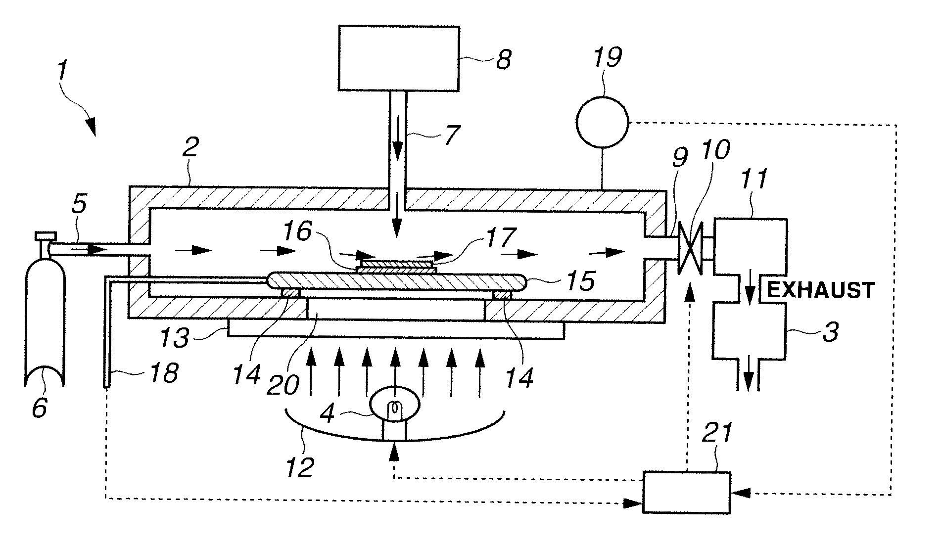
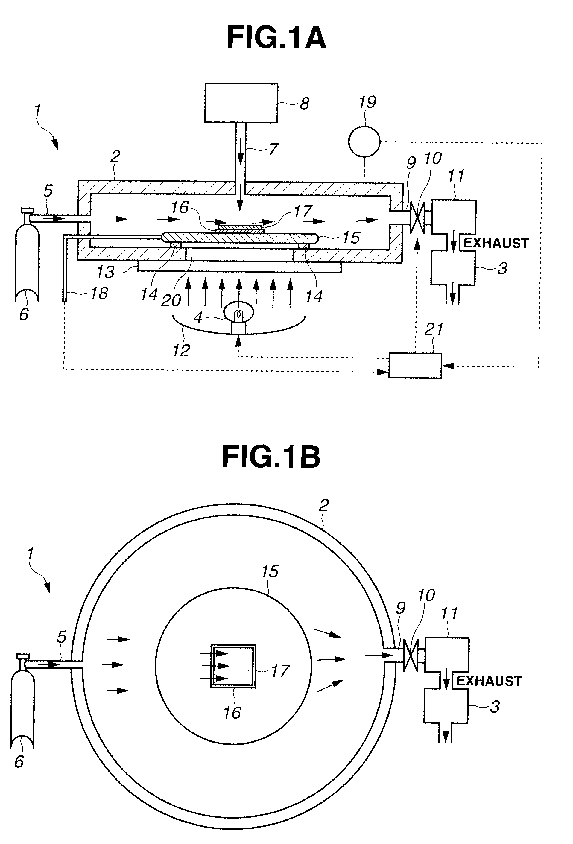
[0035]FIG. 1A is a sectional view schematically showing a system of a resist removal apparatus 1 according to an embodiment of the present invention. FIG. 1B is a plan view schematically showing the resist removal apparatus 1.

[0036]The resist removal apparatus 1 has a chamber 2, a vacuum pump 3 and alight source 4. The chamber 2 holds a substrate 16 coated with a resist 17 which is going to be removed, and ozone gas (O3) and unsaturated hydrocarbon gas are introduced into the chamber 2. As the resist 17, such a resist for ArF (ArF resist), a resist for KrF (KrF resist) and resists for G, I lines (G-line resist, I-line resist) as shown in FIG. 7 are given.

[0037]As can be seen in FIGS. 1A and 1B, the chamber 2 is formed into a cylindrical shape. The chamber 2 is supplied with the unsaturated hydrocarbon gas or fluorine substitution product gas of the unsaturated hydrocarbon from a side face portion, also is supplied with the ozone gas from a ceiling portion. The chamber 2 is designed ...


PUM

PropertyMeasurementUnit
Temperatureaaaaaaaaaa
Pressureaaaaaaaaaa
Concentrationaaaaaaaaaa

Abstract

A resist removal apparatus 1 can remove a resist on a substrate at a low temperature of 90° C. or less. That is, the resist removal apparatus 1 has a chamber 2 which holds a substrate 16 coated with a resist 17 that is going to be removed, and can heat the substrate 16, also into which unsaturated hydrocarbon gas or fluorine substitution product gas of unsaturated hydrocarbon together with ozone gas are supplied at a lower pressure than an atmospheric pressure. An internal pressure of the chamber 2 is controlled so that a temperature of the substrate 16 is 90° C. or less. As the ozone gas, ultra-high concentration ozone gas that is obtained by separating only ozone from ozone-containing gas by a difference of vapor pressure through liquefaction separation and by vaporizing the above ozone again, is given. It is preferable to supply ultrapure water to a treated substrate 16 for cleaning. The chamber 2 is provided with a susceptor 15 that holds the substrate 16. The susceptor 15 is heated by a light source 4 that emits infrared light.

Description

TECHNICAL FIELD[0001]The present invention relates to a technique for removing a resist, particularly a high-dose ion implantation resist, formed on a substrate in a manufacturing process of a semiconductor device.BACKGROUND ART[0002]As the technique for removing the high-dose ion implantation resist on the substrate, for example, they have been disclosed in the following Patent Documents.[0003]In Patent Document 1, a method for plasma processing and its apparatus have a substrate bias application means and a substrate heat application means, and the plasma processing is performed to the substrate using a helicon wave plasma processing. More specifically, a resist mask on the substrate is removed by an ion mode-dominated plasma processing that utilizes a high ion current by the helicon wave plasma and a radical mode-dominated plasma processing by a non-resonant inductively coupled plasma.[0004]In Patent Document 2, a method for plasma processing and its apparatus have a transparent ...

Claims


Application Information

Patent Timeline
IPC IPC(8): H01L21/306
CPCG03F7/42H01L21/31138G03F7/427G03F7/423
Inventor MIURA, TOSHINORI
Owner MEIDENSHA ELECTRIC MFG CO LTD
Why Eureka
Try Eureka