Methods and systems for making reinforced thermoplastic composites, and the products

a technology of thermoplastic composites and reinforced thermoplastics, applied in chemical/physical/physical-chemical processes, coatings, chemistry apparatuses and processes, etc., can solve the problems of high tooling costs, limited use of thermoplastics for vehicle parts, and work done with thermoplastics, so as to improve the elevated temperature performance, reduce moisture, and improve the effect of stiffness

Active Publication Date: 2010-12-02
JOHNS MANVILLE CORP
View PDF8 Cites 48 Cited by
  • Summary
  • Abstract
  • Description
  • Claims
  • Application Information

AI Technical Summary

Benefits of technology

[0016]The methods of the invention produce reinforced thermoplastic composite products having a far greater stiffness than existing reinforced thermoplastic composite products and improved elevated temperature performance, such as in a temperature range of about 50 to about 80 degrees C. Another advantage of the methods of the invention is that the molded products can be de-molded while still very hot, and also before polymeri

Problems solved by technology

Some work was done with thermoplastics, but this was limited due to the extremely high tooling costs incurred for injection molding tooling, and because the viscosity of molten thermoplastics is too high for conventional forming processes used to make large and/or structural GFRC parts, such processes as RIM (Reactive Injection Molding), SRIM (Structural Reactive Injection Molding), RTM (Resin Transfer Molding), VARTM (Vacuum Assisted Resin Transfer Molding), SMC (Sheet Molding Compound), BMC (Bulk Molding Compound), spray-up forming, filament winding, LFI (Long Fiber Injection molding) and pultrusion, much work was being done on thermoset GFRC.
The resultant mixture is formed into a molding material that is supplied to a press or injection molding system to be formed with very expensive tooling into GFRC parts.
Because of these difficulties, the use of therm

Method used


Image

  • Methods and systems for making reinforced thermoplastic composites, and the products
  • Methods and systems for making reinforced thermoplastic composites, and the products
  • Methods and systems for making reinforced thermoplastic composites, and the products

Examples


example 1

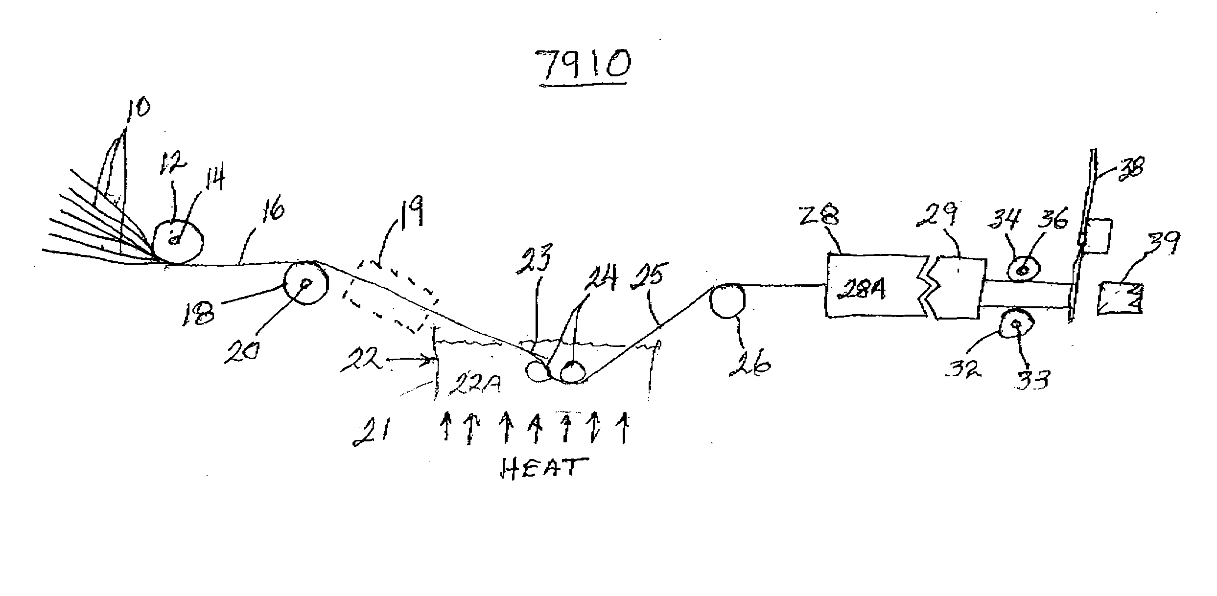
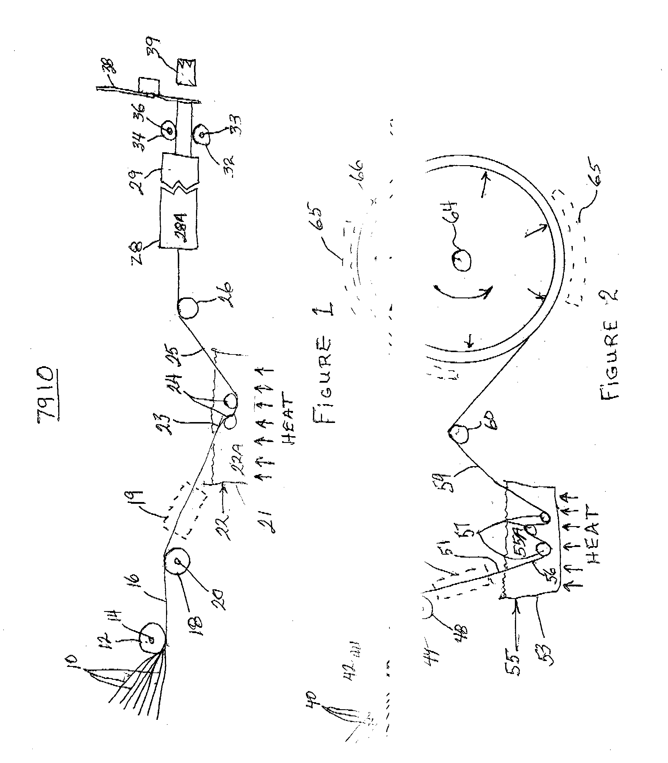
[0036]Referring to FIG. 1, continuous, dry glass fiber strands 10, the glass fibers in the strands 10 having been previously sized with a sizing composition comprising an amount of 2-oxo-N-(3-(triethoxysilyl)propyl)azepane-1-carboxamide (compound 3 in reaction scheme A above) within the suitable range disclosed above, a conventional amount of any conventional organosilane normally used in glass fiber sizings, and a conventional amount of one or more conventional glass fiber lubricants conventionally used in glass fiber sizings, are pulled from a plurality of roving packages on racks (not shown) by the puller in the process. The glass fibers in this example are E glass fibers having an average diameter of about 20 micron. The glass fiber strands 10 are pulled over a multi-grooved guide roll 12 supported on a free wheeling mandrel 14 with one or more strands 10 being in each groove to spread out the strands 10 into a horizontal array 16 suitable for impregnation with a monomer-catalys...

example 2

[0038]This example illustrates the production of a glass fiber-reinforced polyamide-6 using a modified, according to the invention, resin transfer molding (RTM) process or a modified, according to the invention, reinforced reaction injection molding (RRIM) process. A glass fiber preform is made, having or approximating the shape of the desired product, at least in two dimensions, using any conventional manner except that the glass fibers in the glass fiber strands used in the glass fiber products making up the preform, chopped and / or continuous fiber strands, have been sized with a sizing composition comprising a sufficient amount of 2-oxo-N-(3-(triethoxysilyl)propyl)azepane-1-carboxamide, or other suitable silane coupling agent, 0-70 wt % of a polyurethane emulsion or a suitable mixture of emulsions, 10-50 wt % of a lubricant or mixture of lubricants, and optionally, 0-50 wt % of any other conventional required or desired additives. By sufficient amount is meant an amount that will...

example 3

[0042]Reinforced thermoplastic composite products can also be made using modified BMC processes. In this method, the thermoplastic precursor monomer(s), such as a lactam monomer, and one or more catalyst compounds as disclosed above, is heated to temperature range above the melting point of the monomer(s) and below the reaction temperature of the polymerization and placed into a BMC type or any mechanical mixer that can, optionally, also be heated or cooled. While the mixer is turning, reinforcement in the form of one or more of fibers, flakes and chopped strands of fibers, the fibers or flakes having on their surfaces one or more of the activator compounds, such as that used in Example 1, is slowly added to the monomer mixture while mixing until all reinforcement is added and thoroughly dispersed in the monomer mixture, to form a BMC compound. If desired, the temperature of this mixture can be maintained at the temperature of the monomer / catalyst mixture using either preheated rein...


PUM

PropertyMeasurementUnit
Fractionaaaaaaaaaa
Pressureaaaaaaaaaa
Temperatureaaaaaaaaaa

Abstract

Various methods and systems of making inorganic fiber/flake reinforced composites having a thermoplastic matrix are disclosed. The methods use systems similar to those used to make inorganic fiber/flake reinforced products having a thermoset matrix, but the systems and methods are modified to use thermoplastic precursor monomer(s) followed by in situ polymerization of the monomer(s) during and/or following forming of the desired shape of the products. These methods permit the manufacture of superior inorganic fiber reinforced thermoplastic matrix composites in large and very large shapes heretofore not possible, or practical.

Description

BACKGROUND OF THE INVENTION[0001]In the 1980's there was a mighty development effort by the automotive companies to replace many metal parts of vehicles with glass fiber reinforced composites (GFRC) to reduce weight and increase gas mileage. Some work was done with thermoplastics, but this was limited due to the extremely high tooling costs incurred for injection molding tooling, and because the viscosity of molten thermoplastics is too high for conventional forming processes used to make large and / or structural GFRC parts, such processes as RIM (Reactive Injection Molding), SRIM (Structural Reactive Injection Molding), RTM (Resin Transfer Molding), VARTM (Vacuum Assisted Resin Transfer Molding), SMC (Sheet Molding Compound), BMC (Bulk Molding Compound), spray-up forming, filament winding, LFI (Long Fiber Injection molding) and pultrusion, much work was being done on thermoset GFRC. In the injection molding process chopped glass fibers and pellets of a thermoplastic polymeric resin ...

Claims


Application Information

Patent Timeline
IPC IPC(8): C08K3/40B29C33/02B01J19/00
CPCB29B15/125B29C70/32B29C70/521B29C70/545B29K2101/12B29K2105/12C08K7/14B29C70/36B29K2077/00B29K2105/0002B29K2105/0014C08K7/28
Inventor GLEICH, KLAUS FRIEDRICHASRAR, JAWEDBURGHARDT, THOMAS E.TADEPALLI, RAJAPPA
Owner JOHNS MANVILLE CORP
Why Eureka
Try Eureka