Abrasive compact

a technology of abrasives and compacts, applied in the field of abrasive compacts, can solve the problems of difficult to make diamond tools of different shapes and sizes purely from cutting and shaping diamonds, application temperature may be limited, and the reaction sintering to obtain fully dense compacts is only relatively straightforward

Inactive Publication Date: 2010-12-09
ELEMENT SIX ABRASIVES
View PDF2 Cites 76 Cited by
  • Summary
  • Abstract
  • Description
  • Claims
  • Application Information

AI Technical Summary

Benefits of technology

[0022]According to a first aspect to the present invention there is provided an abrasive compact comprising a mass of diamond particles and a silicon containing binder phase wherein the diamond particles are present in an amount less than 75 volume % and the binder phase contains less than 5 volume % unreacted (elemental) silicon or silicide. Preferably the diamond particles are present in an amount of more than 5, more preferably 10, and most preferably 20 volume %; but less than 75, more preferably less than 70 volume %. The compact binder phase is characterised in that, whilst it i

Problems solved by technology

Due to its high hardness, it is difficult to make diamond tools of different shapes and sizes purely from cutting and shaping diamond.
SIC does not react with diamond and hence the composite material can be used at temperatures above 1000° C. However, the application temperature may be limited by the melting temperature of silicon if some unreacted silicon is present in the final product.
Reaction sintering to obtain fully dense compacts is only relatively straightforward under the high-pressure high-temperature (HpHT) conditions typically associated with diamond synthesis.
Under low pressure conditions (such as Hot Pressing (HP) and Hot Isostatic Pressing (HIP)), the volume decrease associated with the local formation of SiC from the intermingled silicon source and diamond may well result in residual porosity.
This requirement for high or ultra high pressure limits the application of these materials due to production costs and the limited sizes and shapes accessible with this technique.
The limitation imposed by this pore size and density requirement means that infiltration has been chiefly employed for the manufacture of larger-grained diamond compacts, or those with a wide diamond grain size distribution.
This pore retention problem is exacerbated by the ongoing fo

Method used


Image

  • Abrasive compact
  • Abrasive compact
  • Abrasive compact

Examples


example 1

[0059]A preform containing diamond powder (average grain size of 1.5 μm) coated with a pyrolytic carbon layer was prepared.

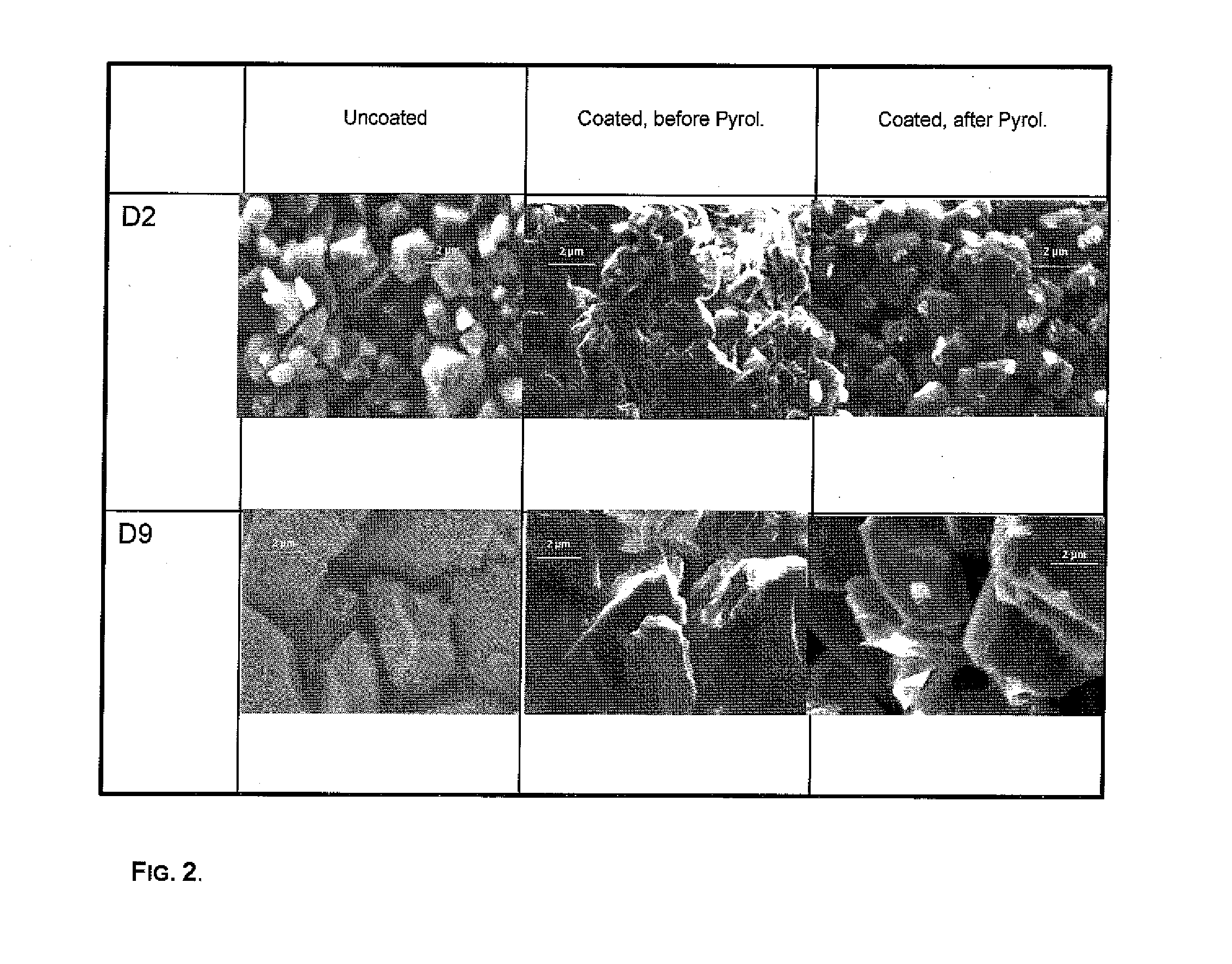
[0060]An amount of phenolic resin to give 10 mass % in the diamond mix, was dissolved in acetone at a concentration of approximately 34.3 g / l. This solution was then mixed with the diamond powder and heated in a water bath to 70-80° C., whilst stirring, to evaporate off the acetone. The resulting agglomerated powder was crushed and screened using a −325 mesh screen. SEM micrographs of the coated grit showed that the resin was homogeneously distributed on the diamond surfaces, both before and after pyrolysis

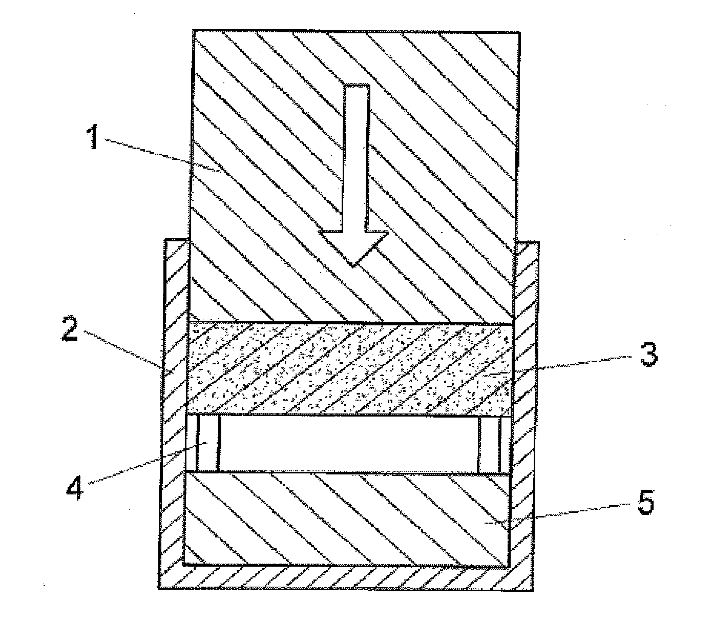
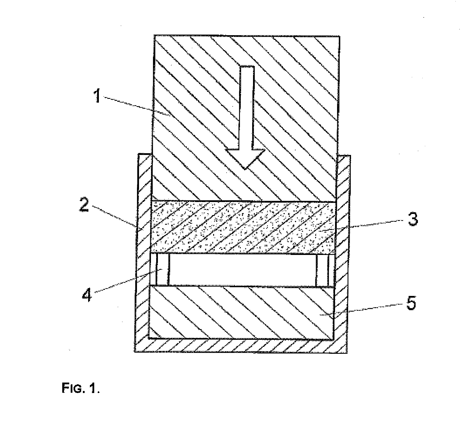
[0061]A green compact was then formed by cold compaction of the screened powder at ca. 60 MPa. This green compact was then heat-treated at 120° C. in air for 18 hours, in order to cure the resin. The resin coating on the diamond was then pyrolysed by heat treatment under argon. The heating upramp cycle was in two parts: initially up to 450° C. at 2° C. / min; fo...

examples 2-7

[0065]Further diamond compacts was prepared according to the method of example 1, save that the diamond average grain size and phenolic resin content were altered as shown in Table A.

TABLE ATable A Summaries of various characteristicsof the compacts produced.DiamondPreformInfiltrationPhase compositiongrain sizeresin contentdepth(volume %)Example(μm)(mass %)(mm)DiamondSiCSi11.5102.5406002910full5347031.551.25———49524651351.520poor———6920poor———716.55full52408

[0066]As is evident from Table A, excess quantities of phenolic resin are undesirable in that they cause a similar pore-blocking effect to that observed without any resin being present. In this case, optimal levels of resin addition at approximately 10 mass % were observed to maximise the infiltration process and reduce the presence of undesirable free silicon.

example 8

[0067]The contents of the paper ‘The low-pressure infiltration of diamond by silicon to form diamond-silicon carbide composites’ as authored by Sigalas, Herrmann and Mlungwane is incorporated herein by reference. For the avoidance of doubt, the paper is set out below:

Abstract

[0068]The infiltration of fine-grained diamond preforms by molten silicon is limited by the blocking of the pores as a result of the volume increase during the reaction of diamond with SiC. Therefore in the present paper the infiltration of preforms made with diamond powders with different grain sizes was investigated. The preforms were prepared using phenolic resin as a binder. With increasing resin content the pore size increases, but the pore volume decreases. As a result the infiltration depth increases strongly for medium resin content. For the fine-grained ˜1.5 μm diamond preforms, a maximum infiltration depth of 2.5 mm is obtained at 10% resin, whereas at 5% resin only 1.25 mm could be infiltrated.

1. Intr...


PUM

PropertyMeasurementUnit
Grain sizeaaaaaaaaaa
Percent by volumeaaaaaaaaaa

Abstract

The invention relates to an abrasive compact comprising a mass of diamond particles and a silicon containing binder phase wherein the diamond particles are present in an amount less than 75 volume % and the binder phase contains less than 2 volume % unreacted (elemental) silicon. The invention further relates to a method of producing an abrasive compact including the steps of forming a feed diamond powder into a diamond preform, interposing a separating mechanism between the diamond preform and a silicon infiltrant source, heating the diamond preform and silicon infiltrant source until the infiltrant is molten and the preform and infiltrant are isothermal and allowing infiltration from the molten silicon infiltrant source to occur into the diamond preform.

Description

INTRODUCTION[0001]This invention relates to a diamond compact body comprising diamond particles bonded together by a silicon-containing binder or bonding phase. Such compacts are well-known in the art and are useful as an abrasive, cutting tool, nozzle or other wear-resistant part. The invention extends to a method of manufacturing such a diamond compact body.BACKGROUND OF THE INVENTION[0002]Diamond is the hardest material known to man. Because of this, it finds extensive industrial application where ultra-hard material properties are needed. Due to its high hardness, it is difficult to make diamond tools of different shapes and sizes purely from cutting and shaping diamond. This has led to the development of diamond composite materials which consist of small diamond grains either sintered together through a liquid phase sintering process, or held together in a matrix by a binder phase material. The former process gives rise to the class of polycrystalline diamond materials (PCD), w...

Claims


Application Information

Patent Timeline
IPC IPC(8): C09K3/14
CPCC04B35/52C04B35/573C04B35/6269C04B35/62839C04B35/6316C04B35/645C04B2235/3826C04B2235/427C04B2235/428C04B2235/48C04B2235/5436C04B2235/5481C04B2235/608C04B2235/616C04B2235/6562C04B2235/721C04B2235/728C04B2235/80C04B2235/96C04B2235/9623F41H5/0492B24D3/14
Inventor SIGALAS, IAKOVOSMLUNGWANE, KEKELETSOHERRMANN, MATHIAS
Owner ELEMENT SIX ABRASIVES
Why Eureka
Try Eureka