Concentrating Solar Energy System for Multiple Uses

a solar energy system and solar energy technology, applied in the field of solar energy systems, can solve the problems of high capital cost, uncompetitive energy production cost without subsidy, and limited success of solar energy production, and achieve the effects of reducing overall energy conversion efficiency, increasing material density, and increasing surface area

Inactive Publication Date: 2010-12-23
STRATOSOLAR INC
View PDF3 Cites 15 Cited by
  • Summary
  • Abstract
  • Description
  • Claims
  • Application Information

AI Technical Summary

Benefits of technology

[0026]Current large scale systems use large arrays of individually steered collecting elements. Robust motors, gears, electrical equipment etc are needed for each collector element, contributing significantly to overall cost.
[0027]The cost proble

Problems solved by technology

Current Concentrating Solar systems suffer from several problems that have limited their success.
Their high capital costs make the cost of the energy they produce uncompetitive without subsidy.
They also have high ancillary costs to compensate for the unpredictability of their energy output and the long transmission distance from the system to the average power user.
Current systems are severely negatively affected by effects of weather such as rain, clouds, moisture and dust in the atmosphere.
This restricts their geographical location to hot dry desert areas which are relatively scarce and far from consumers of electricity.
In addition, even in deserts, bad weather sometimes restricts electric power output availability, necessitating the provisio

Method used


Image

  • Concentrating Solar Energy System for Multiple Uses
  • Concentrating Solar Energy System for Multiple Uses
  • Concentrating Solar Energy System for Multiple Uses

Examples


second embodiment

[0061]FIG. 7B is a schematic of a solar energy conversion system that absorbs the solar energy delivered by concentrator 26 from exit aperture 118 shown in FIG. 6 and converts it into electricity. This embodiment is a combined cycle electricity generation system which uses both a Brayton gas turbine cycle, and a Clausius-Rankine water / steam cycle. This embodiment is more efficient at energy conversion but adds additional cost for the steam cycle elements. The additional elements are boiler heat exchanger 94 that is heated with the exhaust gas from heat engine 84, steam turbine 96, second electricity generator 98, condenser heat exchanger 100, and water pump 102. Ambient heat exchanger 88 is probably not needed or can be much simpler for this combined cycle system.

[0062]A particular advantage of the use of a combined cycle system with a high temperature concentrating solar system is the improved thermal capacity of sensible heat storage system 82. The thermal storage capacity of ther...

first embodiment

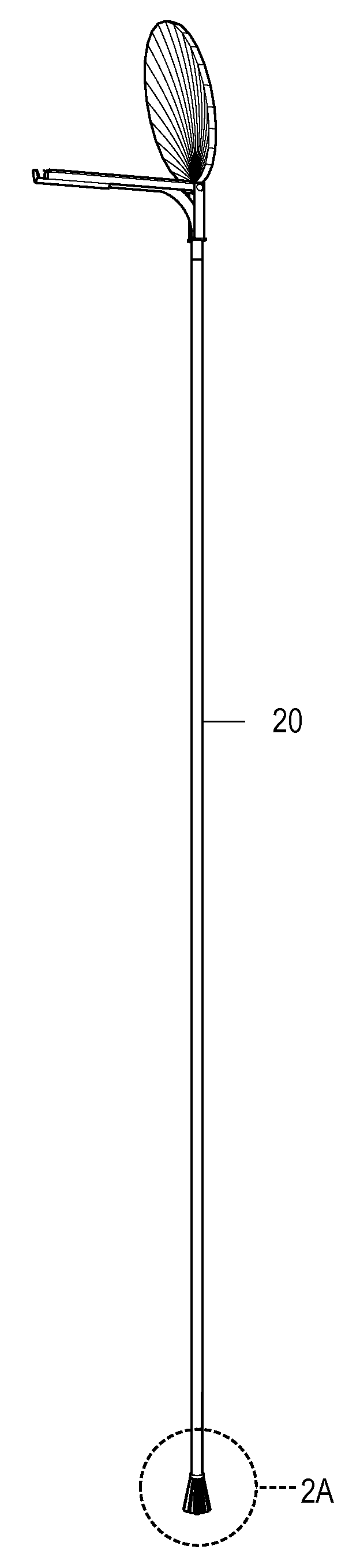
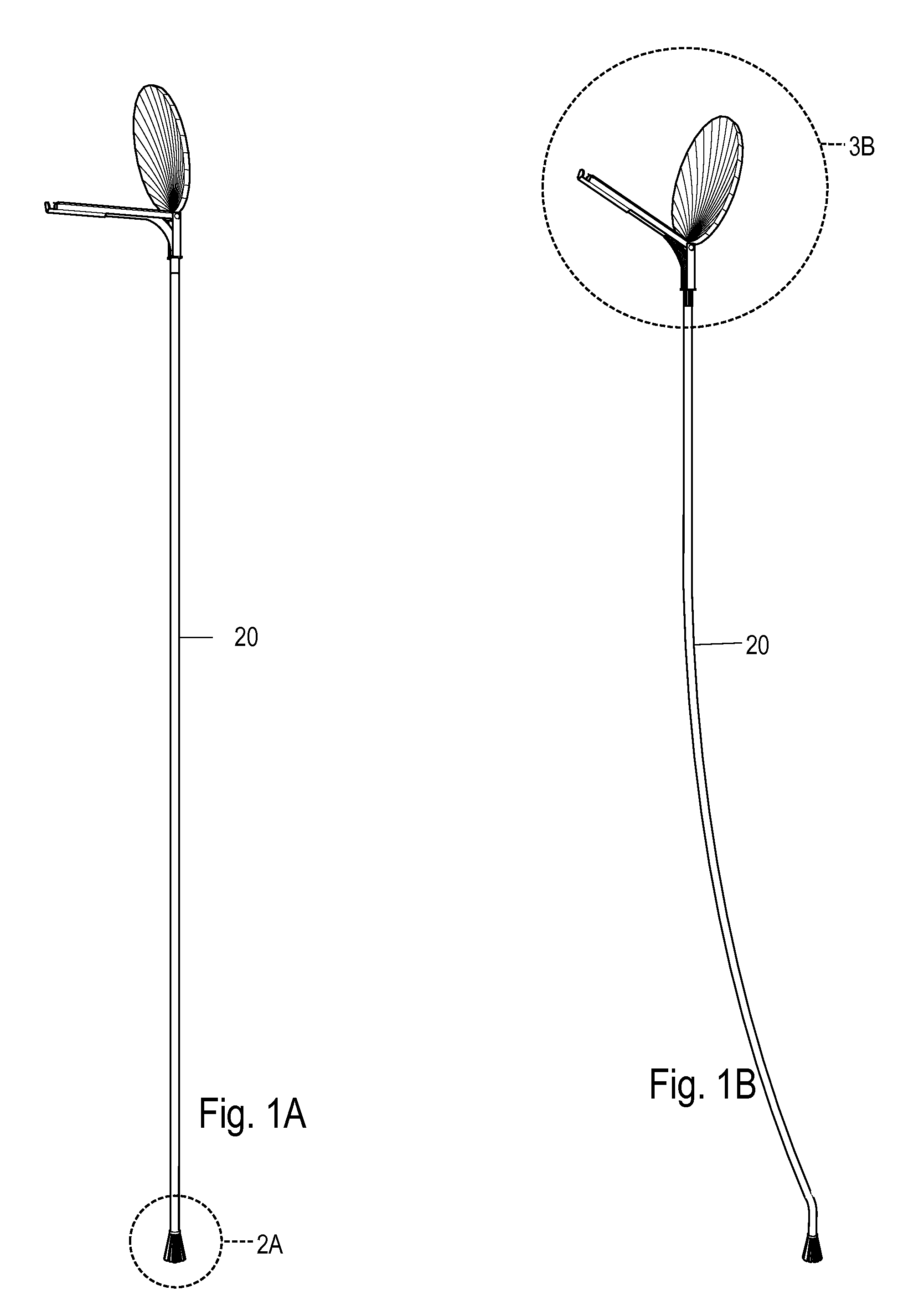
[0066]FIGS. 1A and 1B are perspective views of two positions of a solar concentrator energy system of a It consists of the following:

1) A large, buoyant, segmented, reflecting, parabolic, mirror concentrator, and collimator assembly detailed in FIG. 3B.

2) A flexible hollow buoyant light pipe 20.

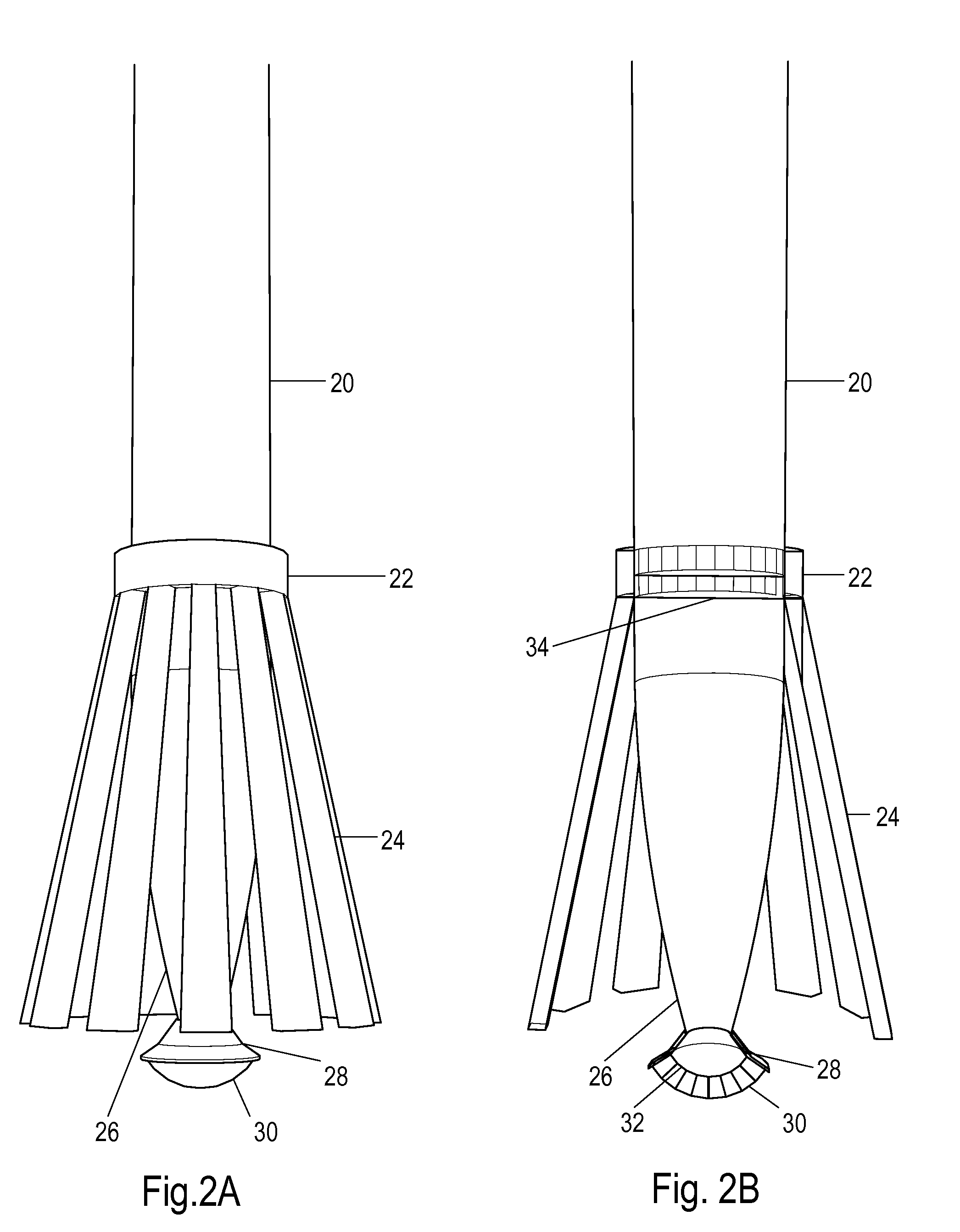
3) A ground based foundation, anchor, optical concentrator and receiver assembly detailed in FIG. 2A.

[0067]FIG. 2A and FIG. 2B show the ground structures of a first embodiment in more detail. Light pipe 20 is attached to anchor ring 22 which is supported by foundation legs 24. Light pipe 20 is a hollow buoyant tube which exerts a considerable vertical upward force on this anchor structure. Transparent membrane 34 is fabricated from polyethylene terephthalate (PET) or other similar transparent film and contains the pressurized gas within the light pipe 20. As is typical for inflated structures the gage pressure is quite low, only a small fraction of an atmosphere. The section of the light pip...


PUM

PropertyMeasurementUnit
Temperatureaaaaaaaaaa
Concentrationaaaaaaaaaa
Transparencyaaaaaaaaaa

Abstract

Systems and methods for concentrating solar energy in the high earth atmosphere and transmitting the concentrated solar energy to the earth's surface. A system includes a light weight solar concentrator, supported by a light weight, rigid, buoyant, structure (36). The buoyant structure is suspended high in the earth's atmosphere above clouds and weather. Steerable mirrors, and/or a steerable structure, enable the concentrator to track the sun. In one embodiment, a buoyant light pipe (20) enables the transmission of concentrated solar energy from the high altitude concentrator to the earth's surface for further use. The system provides concentrated solar energy for use at any location on the earth, such use including generation of electricity via thermal or photovoltaic means and, direct and indirect process heat. The uses of process heat include desalination and hydrogen or methanol or other fuel production. A high solar concentration ratio enables high temperature, and hence high efficiency heat engine operation. With the provision of a thermal storage unit a system can provide utility scale continuous electricity generation and process heat at any location on the planet.

Description

CROSS-REFERENCE TO RELATED APPLICATIONS[0001]Non-provisional application Ser. No. 12 / 430,869, filed on Apr. 27, 2009.FEDERALLY SPONSORED RESEARCH[0002]Not ApplicableSEQUENCE LISTING OR PROGRAM[0003]Not ApplicableBACKGROUND[0004]1. Field[0005]This invention generally relates to solar energy systems, more particularly to, concentrating solar energy systems for power generation and process heat.[0006]2. Prior Art[0007]Concentrating Solar energy systems use optical components such as lenses and mirrors to collect and concentrate the sun's radiation and then absorb it for practical use. The main practical use is to provide high temperature working fluids to drive heat engines that in turn drive electricity generators. Other uses for concentrated sunlight include high intensity photovoltaic electricity generation, direct high temperature “clean” process heat, and indirect high temperature process heat.[0008]A wide variety of designs have been developed to accomplish these goals. The follo...

Claims


Application Information

Patent Timeline
IPC IPC(8): F24J2/38B23P15/26F24J2/30F24S50/20F24S10/30
CPCF24J2/067F24J2/12F24J2/5233F24J2/5271G02B6/0006Y10T29/49355Y02E10/42Y02E10/47Y02E10/52H01L31/0547G02B6/0008F24S20/80F24S23/12F24S23/71F24S25/13Y02A20/142Y02E10/40
Inventor KELLY, EDMUND JOSEPH
Owner STRATOSOLAR INC
Why Eureka
Try Eureka