

Process For Preparing Anhydrous Rare Earth Metal Halides
a rare earth metal and process technology, applied in the field of new technology, to achieve the effects of reducing maintenance, reducing energy consumption, and reducing maintenance costs
- Summary
- Abstract
- Description
- Claims
- Application Information
AI Technical Summary
Benefits of technology
Problems solved by technology
Method used
Image

Examples
example 1
[0054]Dehydration of CeCl3 heptahydrate:
[0055]To a 3 lt / 4 neck round bottom flask fitted with a mechanical stirrer, reflux condenser, Dean and Stark apparatus and calcium chloride drying tube was charged solvent like toluene or xylene (2.2 lit) and cerium chloride heptahydrate (558 g, 1.5 mol) and the slurry was heated to reflux with simultaneous azeotropic water removal. Water removal was continued till almost quantitative water distilled out (187-189 ml) which took almost 48 hrs, resulted in 1.2% moisture content.
[0056]The reaction mass slurry was then cooled to 25 to 30° C. and crystalline solids were filtered and washed with respective solvent (toluene or xylene) under nitrogen blanket. Moisture content of the solid was checked and was found to be in the range of 0.5-1.0%. The cake was preserved under nitrogen atmosphere and activation of CeCl3 is done before use.
[0057]Application of the invention w.r.t. use of CeCl3 with organometalics: The effect of moisture content of the cer...
example 2
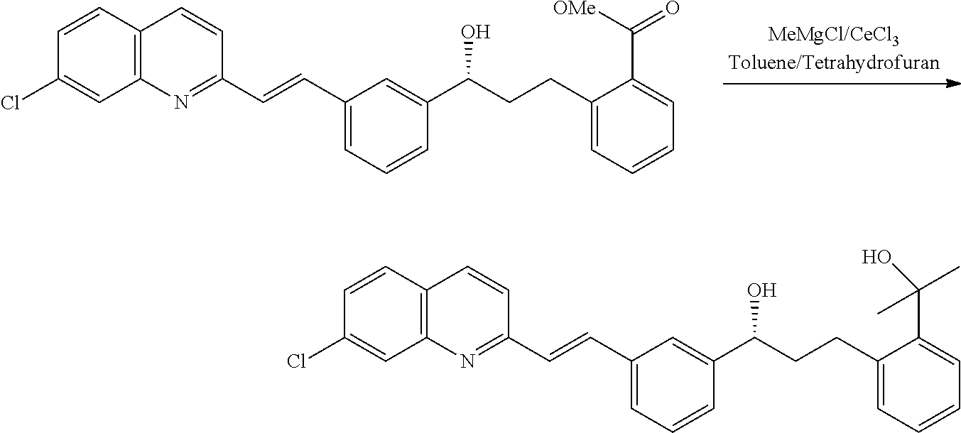
[0058]28.0 g cerium chloride having moisture content of 0.7% stocked under inert atmosphere after azeotropic drying is further activated by refluxing in THF 150 ml for three hours was cooled to −5° C. 81.8 gm methyl magnesium chloride dissolved in 360 ml THF was added in about half an hour keeping the temperature at −5° C. Stirring is continued for 15 minutes. Contents were added with solution of 100 g hydroxy ester dissolved in 200 ml toluene keeping the temperature at −5° C. in 45-50 minutes. Reaction is monitored on HPLC. After the 1.5 hrs reaction mass was observed to contain 1.5% unreacted hydroxyl ester, 3.3% keto impurity and 95.5% of required diol, was taken for work up by the process as available in the art yielded 94.0 g required diol which is taken for further purification.
[0059]Purification: 94.0 g Crude diol is taken into 23S ml toluene and the contents were heated till 60° C. to get a clear solution. 470 ml water was then added at 60° C., cooled gradually to bring down...
example 3
[0060]Dehydration of LaCl3 heptahydrate: To a 3 lt / 4 neck round bottom flask fitted with a mechanical stirrer, reflux condenser, Dean and Stark apparatus and calcium chloride drying tube was charged solvent like toluene or xylene (80 ml) and cerium chloride heptahydrate (20 g, moisture content 34.2%) and the slurry was heated o reflux with simultaneous azeotropic water removal. Water removal was continued till almost quantitative water distilled out (6.8 ml) which took almost 12 hrs, resulted in 8.6% moisture content which on further continuation resulted into 2.5-1.9% moisture content.
[0061]The reaction mass slurry was then cooled to 25 to 30° C. and crystalline solids were filtered and washed with respective solvent (toluene or xylene) under Nitrogen blanket. Moisture content of the solid was checked and was found to be in the range of 1.7%. The cake was preserved under nitrogen atmosphere.
PUM
| Property | Measurement | Unit |
|---|---|---|
| temperature | aaaaa | aaaaa |
| temperature | aaaaa | aaaaa |
| atomic number | aaaaa | aaaaa |
Abstract
Description
Claims
Application Information