
Liquid electrode battery

Active Publication Date: 2011-01-20
MASSACHUSETTS INST OF TECH
View PDF17 Cites 101 Cited by
  • Summary
  • Abstract
  • Description
  • Claims
  • Application Information

AI Technical Summary

Benefits of technology

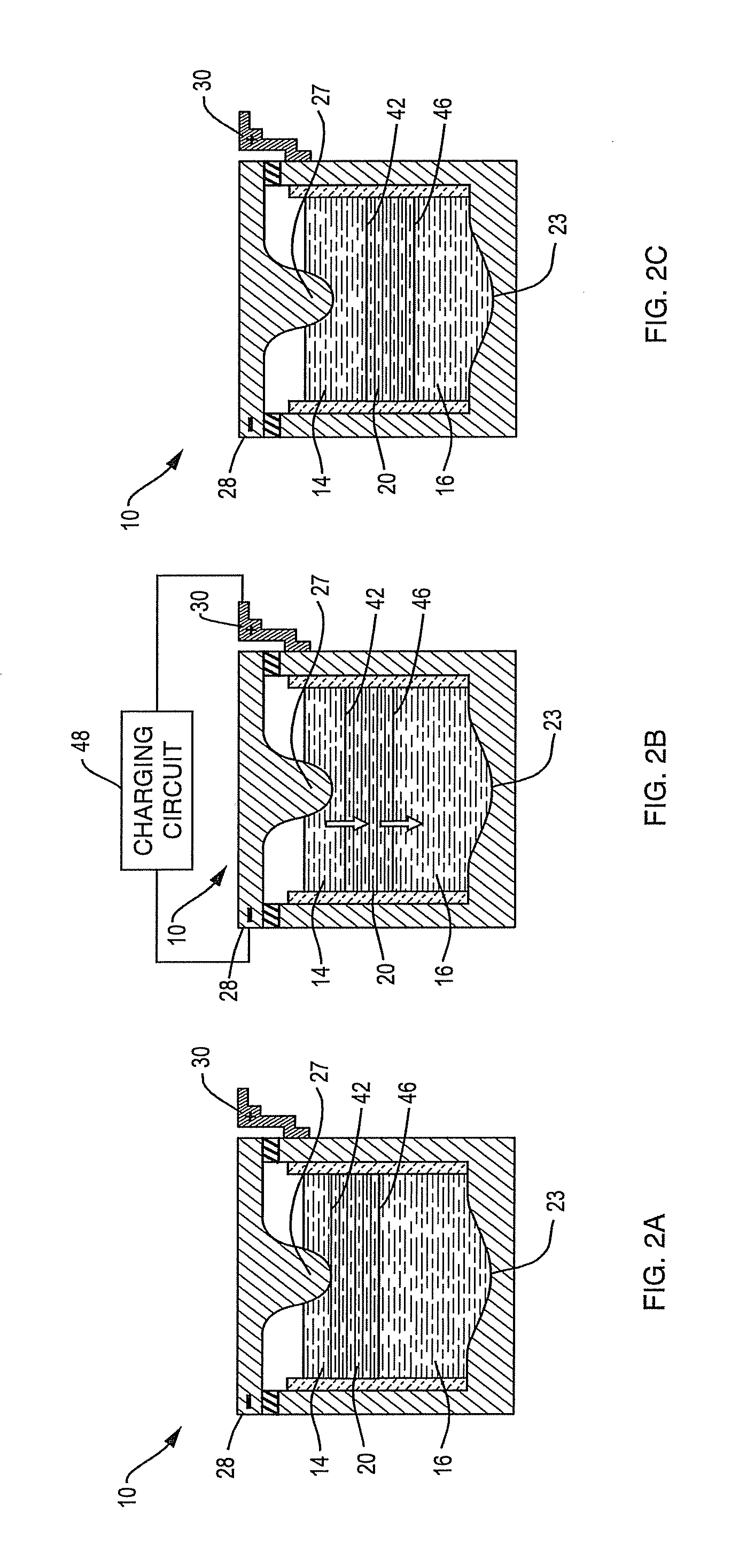
[0011]In another embodiment a method of exchanging energy with an external device comprises providing an external energy exchanging device and a battery. The battery includes a container containing a positive electrode, a negative electrode and an intervening electrolyte, the positive and negative electrodes and the electrolyte existing as liquid material layers in a vertical stack in the container so that adjacent layers form respective electrode/electrolyte interfaces; a positive current collector in electrical contact wit

Problems solved by technology

Balancing supply and demand of electrical energy over time and location is a longstanding problem in an array of applications from commercial generator to consumer.
The supply-demand mismatch causes systemic strain that reduces the dependability of the supply, inconveniencing consumers and causing loss of revenue.
Since most electrical energy generation in the United States relies on the combustion of fossil fuels, suboptimal management of electrical energy also contributes to excessive emissions of pollutants and greenhouse gases.
Renewable energy sources like wind and solar power may also be out of sync with demand since they are active only intermittently.
This mismatch limits the scale of their deployment.
However these facilities are neither compact nor flexibly located.
The short cycle life of lead-acid batteries, on the order of several hundred charge-discharge cycles, limits their performance in uses involving frequent activation over a wide voltage range, such as daily power management.
The batteries do not respond well to fast or deep charging or discharging, which lowers their efficiency and reduces their lifespan.
The electrolyte must be very thin in order to maximize sodium ion conduction, but this makes it mechanically fragile and imposes severe limits on the maximum size of an individual cell.
This, in turn, affects scalability, i.e., large capacity must be achieved through many small cells rather than through few large cells, which greatly increases complexity and ultimately increases the cost of the system.
Cell construction is complication by sodium's violent reaction with water and rapid oxidation in air.

Method used


Image

  • Liquid electrode battery
  • Liquid electrode battery
  • Liquid electrode battery

Examples


Embodiment Construction

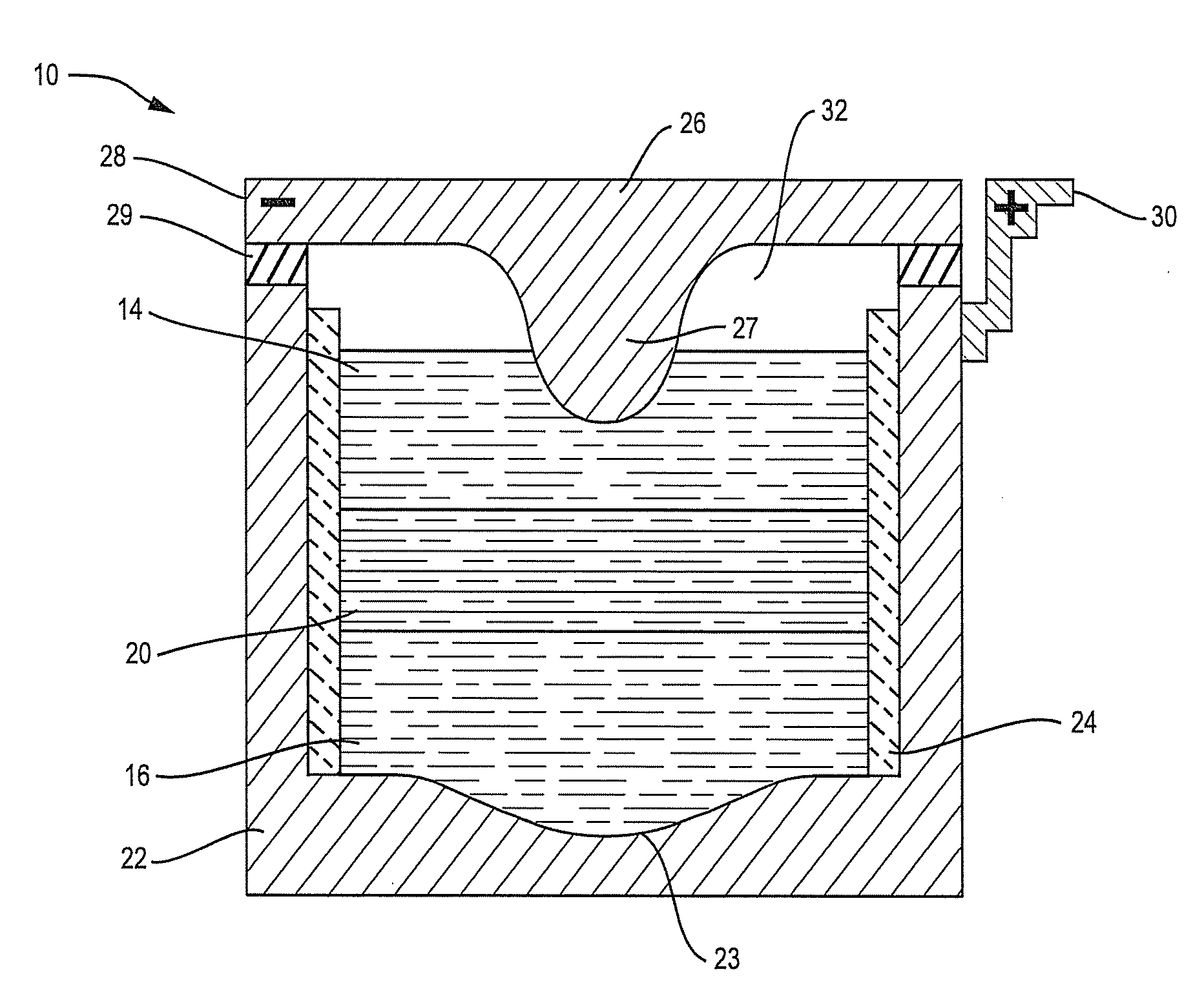
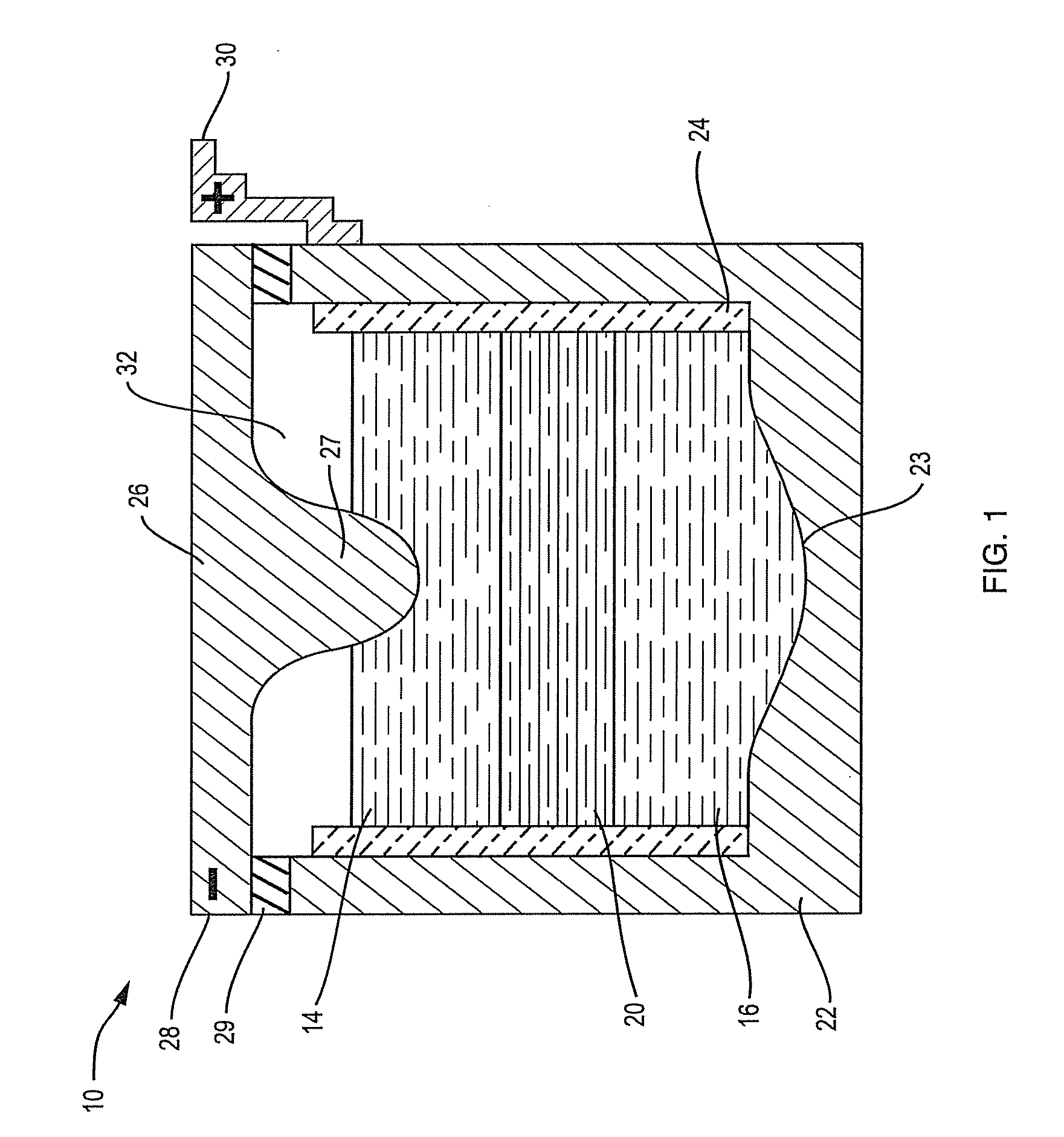
[0028]It will be understood that as used herein, “battery” may encompass individual electrochemical cells or cell units, comprising a positive electrode, a negative electrode and an electrolyte, and configurations comprising a plurality of electrochemical cells. With reference to FIG. 1, an alkaline earth metal ion energy storage cell, or battery, indicated generally at 10, incorporates three distinct liquid constituents: a molten metal body 14 that serves as negative electrode, also referred to as the active metal electrode; an electronically conductive multi-elemental liquid body 16 that serves as positive electrode, also referred to as the alloy electrode; and an intervening ionically conductive electrolyte 20.

[0029]The electrically conductive liquid layers 14, 16 and 20 are confined in an electronically conductive container 22 which illustratively provides mechanical support to an insulating inner sheath 24. The sheath 24 prevents shorting by electronic conduction between the ne...


PUM


Abstract

An electrochemical battery that exchanges energy with an external device. The battery includes a container containing a positive electrode, a negative electrode and an intervening electrolyte, the electrodes and electrolyte existing as liquid material layers in the container at the operating temperature of the battery so that adjacent layers form respective electrode-electrolyte interfaces. Positive and negative current collectors are in electrical contact with the positive and negative electrodes, respectively, both collectors being adapted for connection to the external device to create a circuit through which current flows. A circulation producer in the battery causes circulation within at least one of the layers to increase the flux of material in one layer to an interface with an adjacent layer, thereby giving the battery a greater current / power capability.

Description

RELATED APPLICATION[0001]This application is a continuation-in-part of Ser. No. 12 / 505,937, filed Jul. 20, 2009.BACKGROUND OF THE INVENTION[0002]1. Field of the Invention[0003]This invention relates to electrical energy storage. It relates especially to electrochemical energy storage cell devices or batteries having liquid components and enhanced current-carrying capabilities.[0004]2. Background Information[0005]Balancing supply and demand of electrical energy over time and location is a longstanding problem in an array of applications from commercial generator to consumer. The supply-demand mismatch causes systemic strain that reduces the dependability of the supply, inconveniencing consumers and causing loss of revenue. Since most electrical energy generation in the United States relies on the combustion of fossil fuels, suboptimal management of electrical energy also contributes to excessive emissions of pollutants and greenhouse gases. Renewable energy sources like wind and sola...

Claims


Application Information

Patent Timeline
IPC IPC(8): H01M2/38H01M10/50H01M4/58H01M50/15H01M50/152
CPCH01M2/0252H01M2300/0057H01M2/0456H01M2/1094H01M4/38H01M4/381H01M4/466H01M4/661H01M4/662H01M4/663H01M4/70H01M4/76H01M10/399H01M10/5008H01M10/5042H01M10/5053H01M10/5083H01M10/5087H01M2/0447H01M10/654H01M10/6571H01M10/6554H01M10/617H01M10/658Y02E60/10H01M50/138H01M50/1535H01M50/24H01M50/15H01M50/152H01M50/30H01M4/134H01M4/387H01M2004/027H01M2300/0054
Inventor BRADWELL, DAVIDCEDER, GERBRANDORTIZ, LUISSADOWAY, DONALD R.
Owner MASSACHUSETTS INST OF TECH
Learn More