[0015]Systems and methods for creating an autostereoscopic three-dimensionally perceived image unaided by glasses or headgear include embodiments having a
holographic optical element (HOE) recorded using a
beam shaping device in at least one of the reference and object beam paths to improve uniformity of illumination of the HOE during recording. In one embodiment, a first
beam shaping device that transforms a circular input beam having a generally
Gaussian energy profile to an output beam having a generally uniform energy profile with a generally flat phase-front is positioned in the
reference beam path. A second beam shaping device may be used to transform the circular beam to a square beam in combination with one or more anamorphic optic elements that conform the resulting beam to the
aspect ratio of the HOE and illuminate a first side of the HOE during an
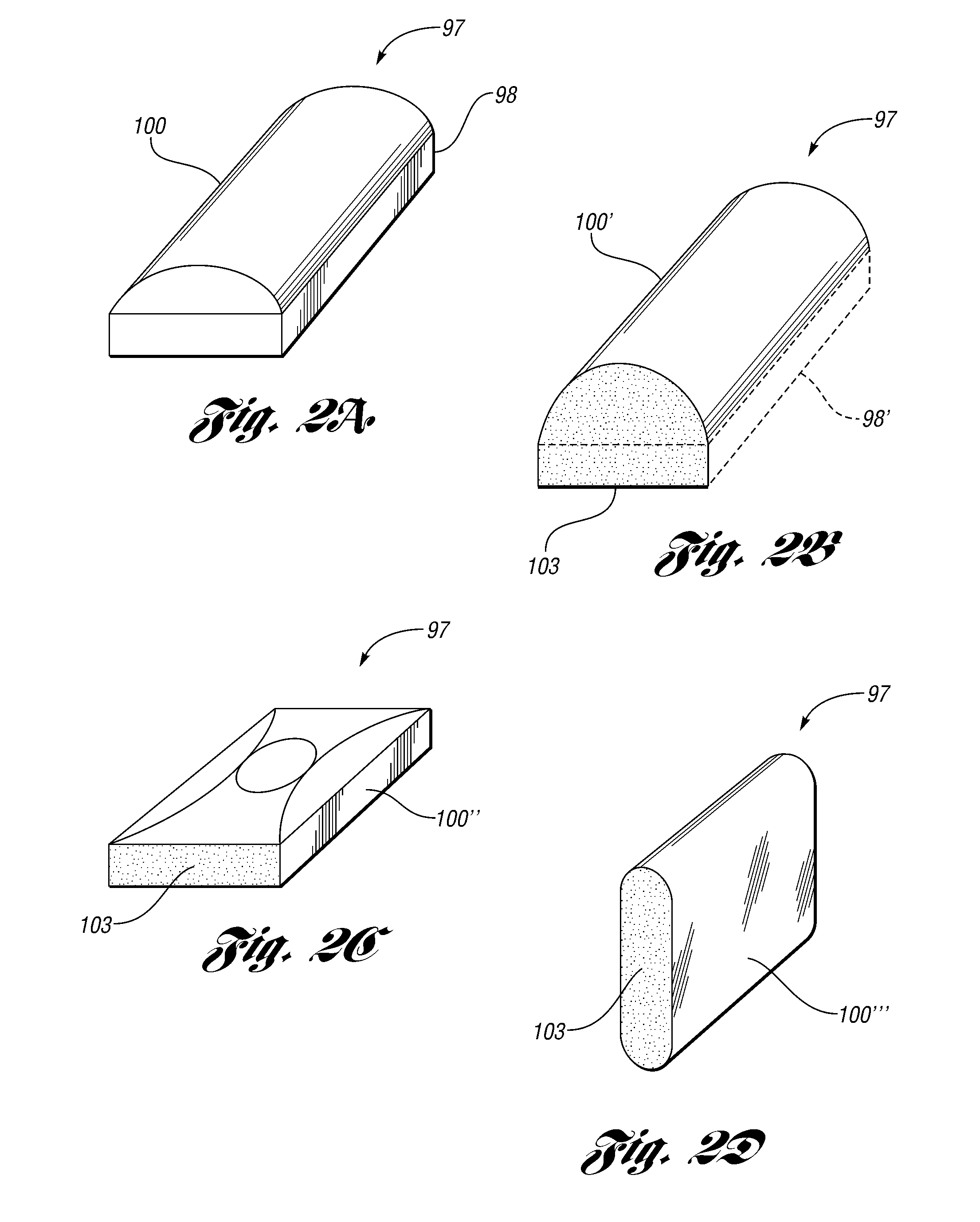
exposure period. A diffuser having randomly distributed suspended nanoparticles with a scattering profile selected for the recording wavelengths that may be shaped to provide a desired eye box geometry is positioned in the object beam path to improve uniformity of illumination of a second side of the HOE during the
exposure period. In various embodiments, the diffuser has a generally planar input surface with either a planar, cylindrical, or ellipsoidal output surface. In one embodiment, the diffuser is implemented by a generally transparent
polymer having 0.1% by weight of randomly distributed
suspended particles of
titanium dioxide with a mean particle size of less than about 25 nm, such that the resulting diffuser is translucent and exhibits achromatic scattering with respect to the recording wavelengths. In one embodiment, the
polymer with suspended nanoparticles is cast in a mold having a desired geometry, cured, and polished prior to use in recording the HOE. Embodiments may also include a beam shaping device positioned upstream of the diffuser to improve uniformity of illumination of the diffuser. Embodiments of a beam shaping device include an optical element shaped as a truncated cone or
pyramid having a reflective interior and positioned with a smaller input aperture than output aperture. The beam shaping device may be used in the object beam and / or the
reference beam to improve uniformity of illumination of the HOE during recording. Other embodiments include a directional diffuser or
homogenizer with a desired eye box geometry to improve transmission efficiency of the object beam. The directional diffuser may be implemented by a holographic element to transform an input beam having a
Gaussian or other non-uniform intensity profile to more uniformly illuminate the HOE during the
exposure period. The directional diffuser may be used in combination with a
beam expander, implemented by a
cylindrical lens in one embodiment, and a second diffuser, implemented by a
ground glass plate in one embodiment, positioned between the
beam splitter and the HOE to provide more uniform illumination of the HOE by the object beam.
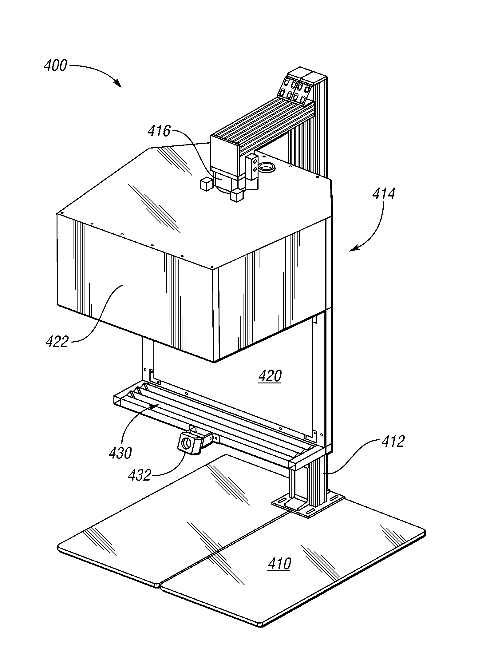
[0016]Systems and methods for generating an autostereoscopic image include at least one
projector having at least one
light source with wavelengths substantially matched to the recording wavelengths of the HOE. In one embodiment, a stereo
projector includes dual output lenses having central axes separated by a distance corresponding to a desired average intra-
pupillary distance (multiplied by the ratio of the projector-screen / screen-viewer distance) of intended viewers. The stereo projector illumination sources are powered by a common power supply with passive
convective cooling so that no cooling fan or other
forced air cooling is required. In another embodiment, two substantially identical projectors are used. Projectors may include LED sources having peak wavelengths closely aligned or matched with the
laser wavelengths used during recording of the HOE. In some embodiments, passbands of the HOE are modified by
emulsion shrinkage. In one embodiment have recording wavelengths of 647 nm, 532 nm, and 476 nm, an LED projector includes closely aligned or substantially matched wavelengths of 637 nm, 518 nm, and 462 nm. Embodiments include projectors having optical keystone correction provided by a telecentric
image plane projection lens system that may be supplemented with digital keystone, gamma, and / or other corrections provided by
integrated electronics or an
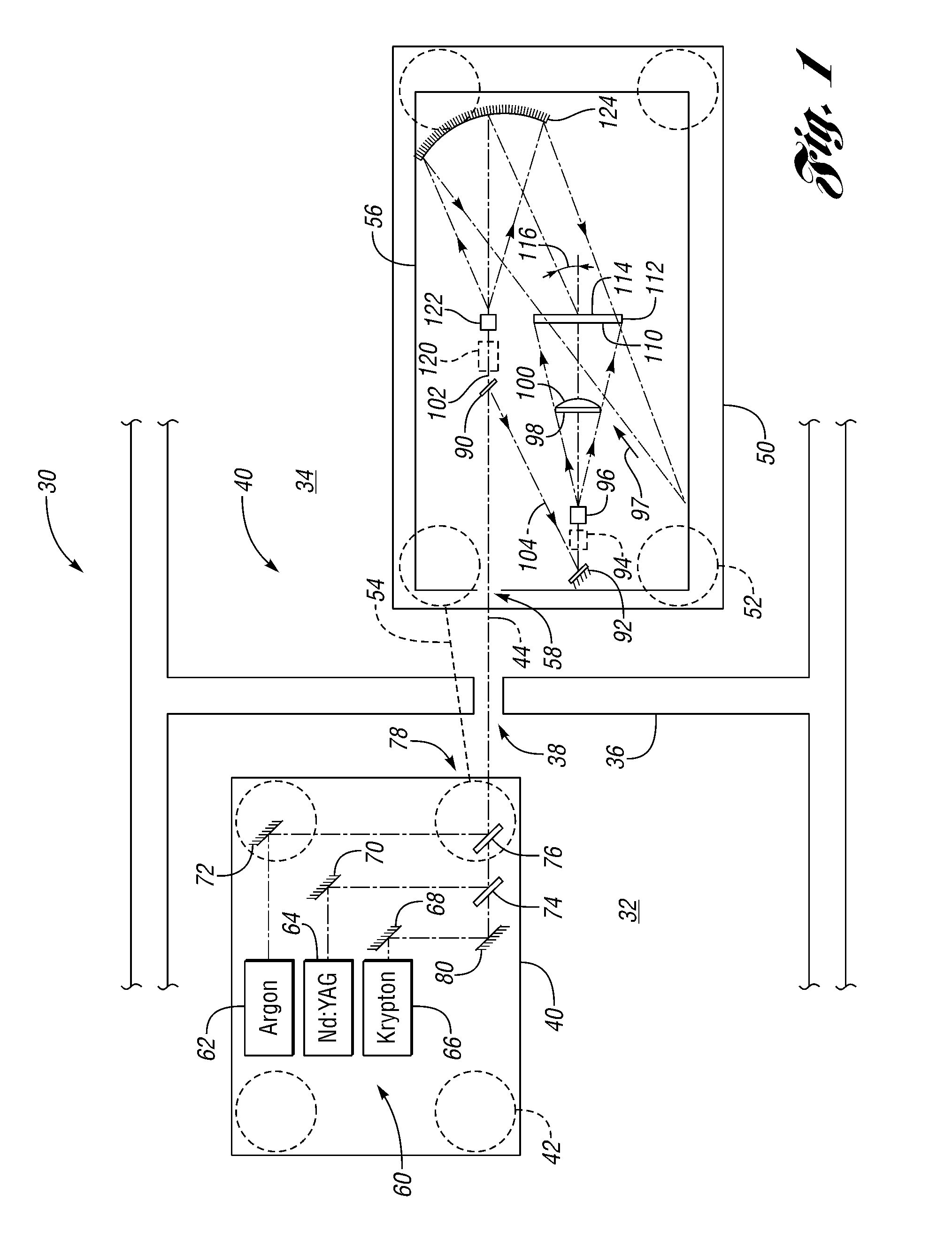
external image processing card, box, or similar device. The systems and methods according to various embodiments of the present disclosure project first and second substantially overlapping images onto a reflection HOE having a holographically recorded interference pattern captured within a single layer panchromatic photosensitive material during recording with at least one beam shaping device positioned in a reference beam and / or object beam path to improve uniformity of illumination and reduce or eliminate
vignetting. The interference pattern captured in the
photographic emulsion is produced by interference between mutually coherent object and reference beams of at least three lasers having wavelengths substantially corresponding to the illumination source of the at least one projector. The HOE illuminated by object and reference beams incident from opposite sides is then processed or developed and sealed to produces a reflection HOE screen illuminated from the viewing side by the at least one projector during use.
[0022]Embodiments according to the present disclosure have various associated advantages. For example, embodiments of the present disclosure provide real-time stereo images to corresponding eyes of at least one viewer to produce a three-dimensionally perceived image without viewing aids, such as glasses or headgear. Various embodiments according to the present disclosure provide real-time viewer position detection and
image display synchronization to allow the viewer to move while staying within predetermined eye-boxes so that
perception of the three-dimensional image is unaffected by viewer movement. Use of a reflection holographic element provides higher resolution and improves color fidelity of reflected images, both of which are desirable for a number of applications, such as
medical imaging,
video gaming, and personal entertainment devices, for example. Use of a beam shaping device in at least one of the reference and object beam paths during recording of a holographic optical element according to various embodiments of the present disclosure provides more uniform illumination to reduce or eliminate
vignetting. Use of a directional diffuser rather than a
ground glass plate or apodizer provides significant improvements in object beam efficiency.

