Integrated gasification combined cycle (IGCC) power plant steam recovery system

Inactive Publication Date: 2011-02-17
GENERAL ELECTRIC CO
View PDF15 Cites 13 Cited by
  • Summary
  • Abstract
  • Description
  • Claims
  • Application Information

AI Technical Summary

Problems solved by technology

Fouling typically increases as a function of operating time, and a significant amount of the lost heat transfer capability can be recovered by a shutting down and restarting the gasifier, which results in knocking off the thick particulate layer attached to the heat transfer surfaces.
This resulted in wasted energy and inefficiencies.
Excess heat or steam is typically vented, decreasing the efficiency of a plant.
Process deman

Method used


Image

  • Integrated gasification combined cycle (IGCC) power plant steam recovery system
  • Integrated gasification combined cycle (IGCC) power plant steam recovery system
  • Integrated gasification combined cycle (IGCC) power plant steam recovery system

Examples


Example

The detailed description explains embodiments of the invention, together with advantages and features, by way of example with reference to the drawings.

DETAILED DESCRIPTION OF THE INVENTION

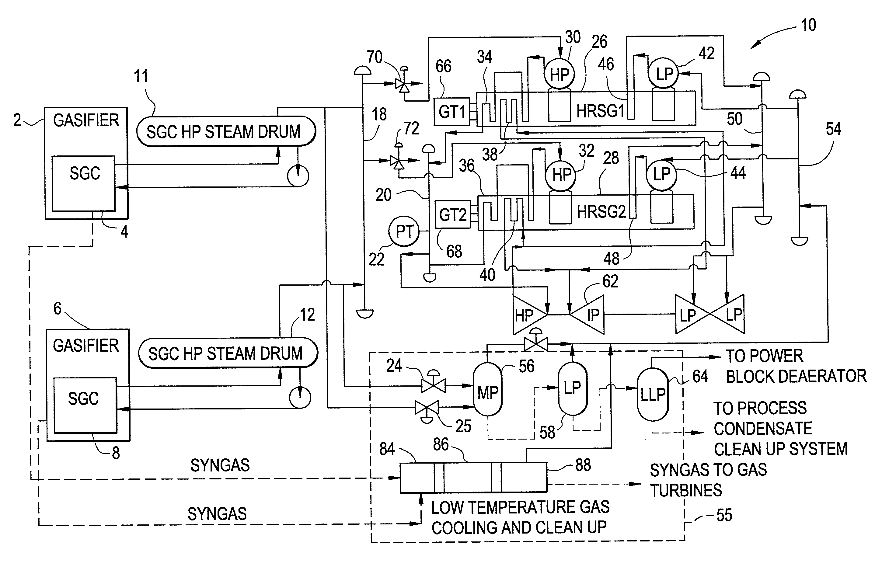
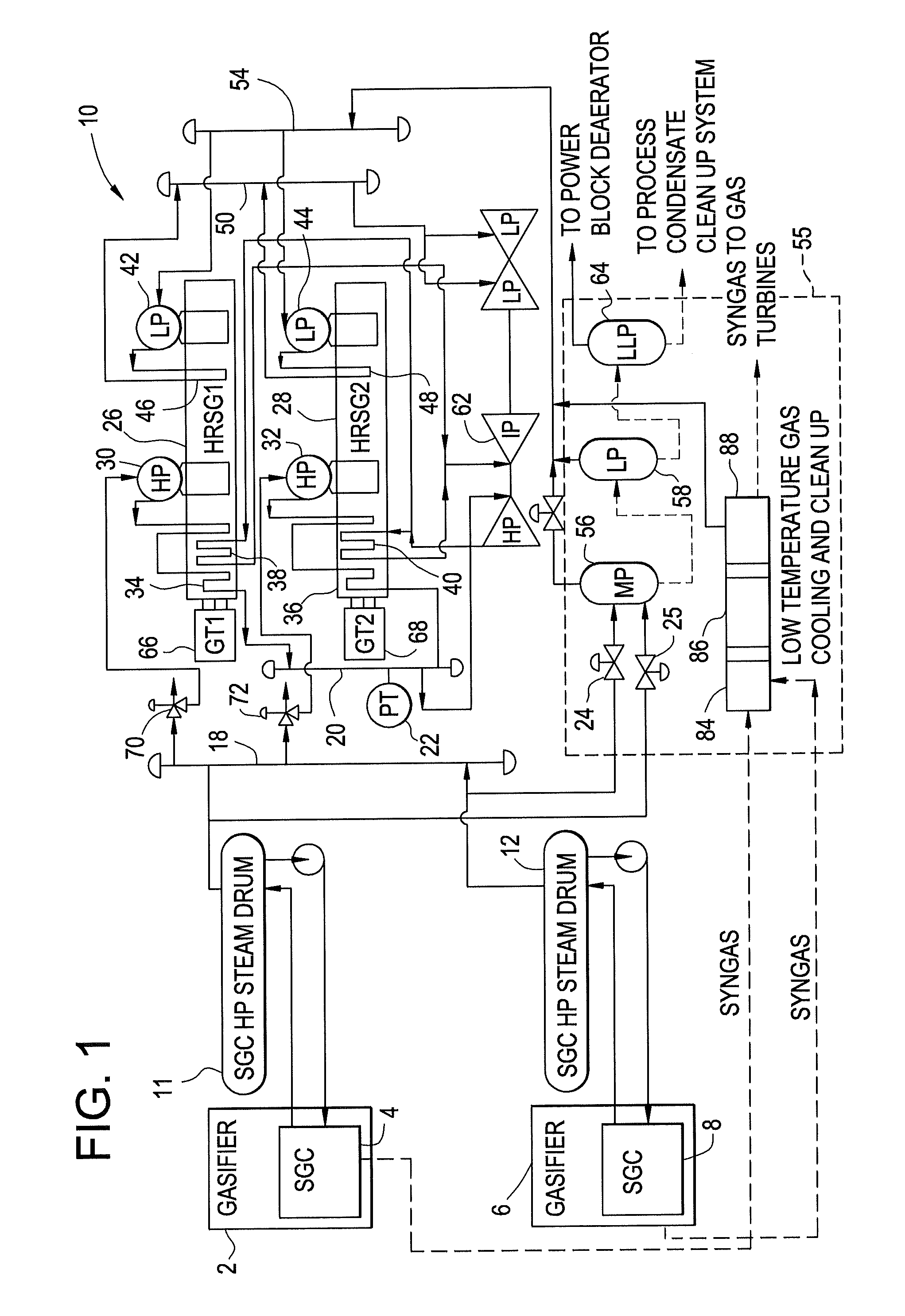
Referring now to FIG. 1, an overview of the gasification process will now be described. In the gasification process, the dirty syngas discharges from a gasifier 2, 4 at approximately 2000° F. to 2500° F. temperature and it is required to be cooled to approximately 100° F. prior to the cleanup process. The syngas cooling is accomplished in three stages: (1) high temperature cooling in a syngas cooler (SGC) 4, 8 by generating high pressure (HP) saturated steam in a syngas cooler high pressure steam drum (SGC HP steam drum) 11, 12, (2) quenching and scrubbing for cooling and particulate removal by direct contact with water, and (3) low temperature gas cooling (LTGC) by generation of low pressure (LP) saturated steam in syngas cleanup systems 84, 86 and 88. The HP saturated steam generated by the syng...


PUM


Abstract

In an integrated gasification power plant a steam recovery system is provided. The system enables power generation equipment designed for a predominant fuel and operating condition to efficiently utilize additional steam generation by syngas coolers when heat transfer surface condition or fuel characteristics enable additional steam generation. The system can detect excess steam generation, integrate it with the syngas cleaning process and transmit it to the power generation equipment. The system results in a low cost power generation system which is capable of efficiently operating with a wide range of fuels and a wide rang of operating conditions.

Description

BACKGROUND OF THE INVENTIONThe subject matter disclosed herein relates to a plant steam system for use with an Integrated Gasification Combined Cycle (IGCC) plants utilizing various coal petroleum coke, gas, or liquid fuel ranges and taking into account fouling characteristics of the Syngas Cooler (SGC) to improve installed cost and performanceIn IGCC plants, clean syngas is produced from partial oxidation of solid or liquid fuels to generate power in a combined cycle application that is integrated for heat recovery with a gasification island. The plants typically include a process island, that is responsible for syngas production, steam generation, water treatment, syngas cleanup and sulfur removal; and a power island, that includes one or more gas turbines and Heat Recovery Steam Generators (HRSG), steam turbine, cooling tower and condenser which operates in accordance with typical combined cycle applications. The heat integration, in which steam is exported to the power island fr...

Claims


Application Information

Patent Timeline
IPC IPC(8): F01K23/10F02C3/28F02C6/04F01K19/00F01K23/16
CPCC10J2300/1675Y02E20/16F01K23/106F05D2220/722Y02E20/18C01B3/36C10J3/721C10J3/86C01B2203/025C01B2203/0877C01B2203/0894C01B2203/84C10J2300/1653C10J2300/1884C10J2300/1892F01K23/067Y02P20/129
Inventor BOMMAREDDY, SAMPATH KUMARHOLLAND, DOUGLAS KIRKJONES, CHARLES MICHAELKIRCHHOF, DARRIN GLENSTOREY, JAMES MICHAELTOMLINSON, LEROY OMAR
Owner GENERAL ELECTRIC CO
Why Eureka
Try Eureka