
Method of depositing protective coatings on turbine combustion components

a technology of protective coatings and combustion components, which is applied in the direction of superimposed coating process, turbines, lighting and heating apparatus, etc., can solve the problems of high temperature durability of engine components, high requirements for components, and high requirements for superalloys protected by overlay coatings. , to achieve the effect of reducing the number of requirements

Inactive Publication Date: 2011-03-03
GENERAL ELECTRIC CO
View PDF7 Cites 24 Cited by
  • Summary
  • Abstract
  • Description
  • Claims
  • Application Information

AI Technical Summary

Benefits of technology

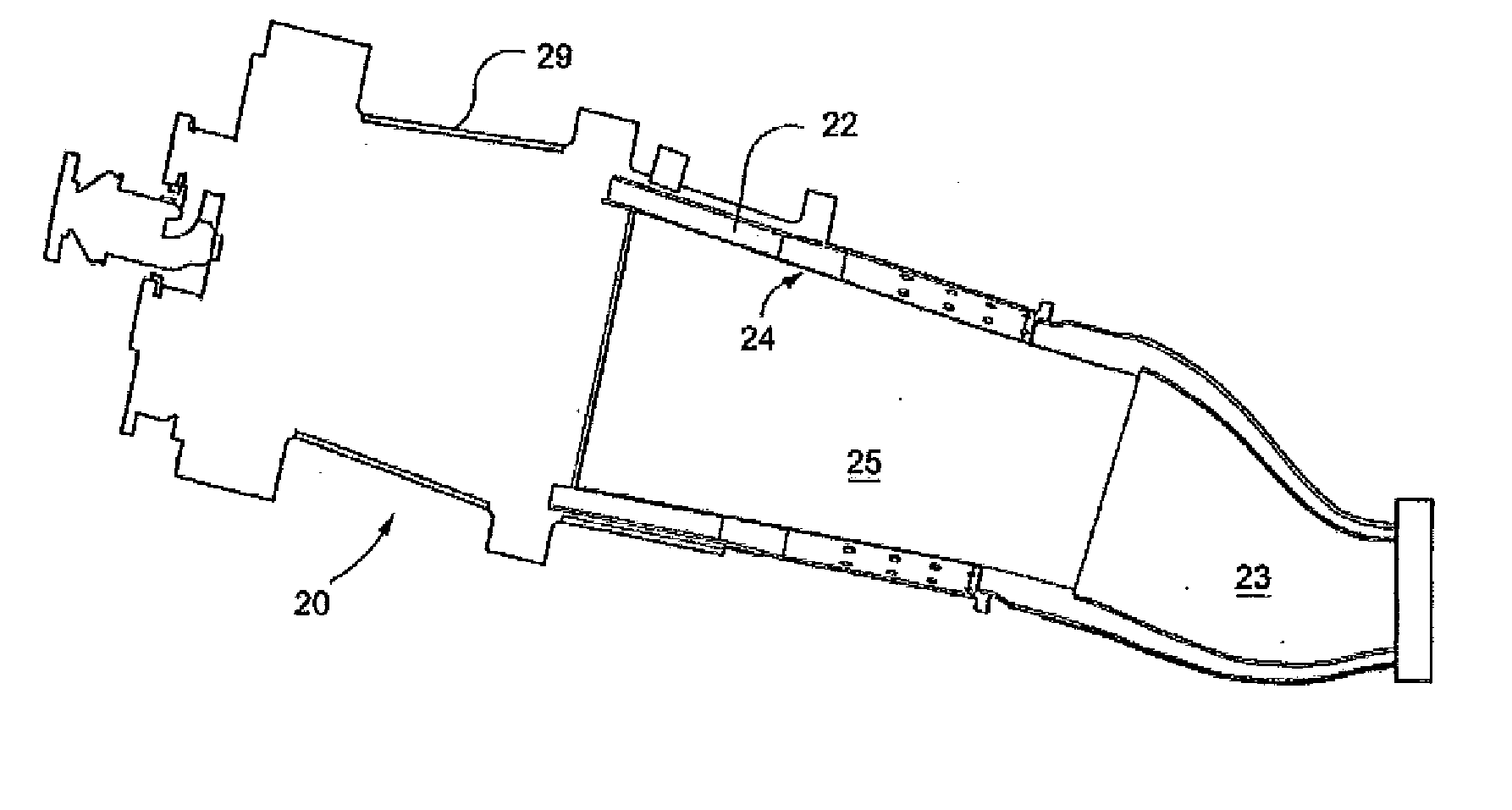
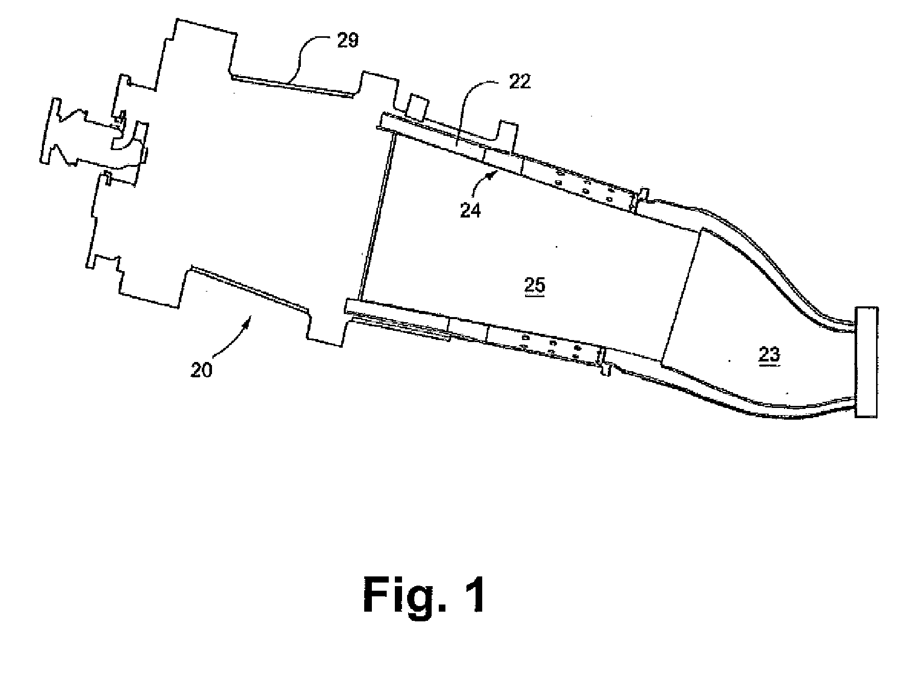
[0012]The present invention provides a method for high velocity air plasma spraying (HV-APS) application of a protective coating system, such as a bond coat with or without an overlying ceramic thermal barrier coat, to a superalloy metal substrate. The invention may be advantageous in any application wherein a thermal bond coat is desired, such as the automotive industry, and the like. The invention has particular usefulness in a gas turbine environment for coating any manner of turbine component, including shrouds, buckets, nozzles and combustion liners, caps, and so forth.

Problems solved by technology

However, as operating temperatures increase, the high temperature durability of the components of the engine must correspondingly increase.
Nonetheless, superalloys protected by overlay coatings often do not retain adequate mechanical properties for components located in certain sections of a gas turbine engine, such as the turbine, combustor and augmentor.
The latter requirement is particularly demanding due to the different coefficients of thermal expansion between materials having low thermal conductivity and superalloy materials typically used to form turbine engine components.
However, these systems are relatively complex and require a significant capital outlay.
The systems require high power consumption equipment, multiple spraying and vacuum chambers for components of different size, and involve time consuming process cycles.
Coating of gas turbine components by VPS techniques can be economically unfeasible.
However, the present commercially available HVOF guns and system are not well suited for turbine combustion components.
In particular, the conventional HVOF guns are relatively long and require a separation distance from the surface being coated of from about 8 to about 15 inches and, thus, do not fit into the relatively small inside diameters of the turbine combustion components.
Thermico Gmbh & Co KG of Dortmund, Germany, has developed a small-size HVOF gun that uses even finer particles (<20 μm), which are expensive and not readily available.
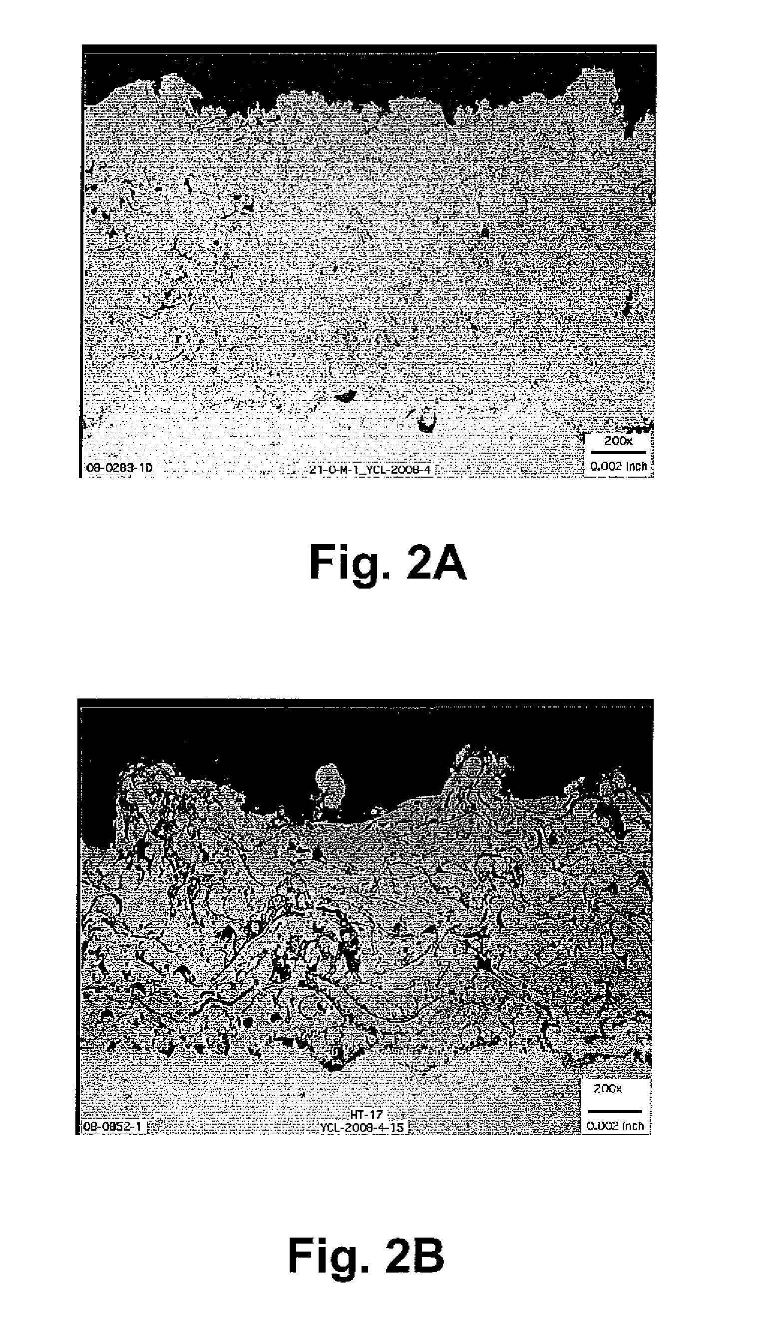
The finer particles results in HVOF-applied bond coats with relatively smooth surface roughness (an undesired characteristic).
Although APS-applied bond coats provide better TBC adhesion due to their roughness, because the APS bond coats are deposited at an elevated temperature in the presence of air, they inherently contain a high oxides content and are more prone to thermal growth oxidation (TGO) because they do not form a continuous oxide scale.
Also, APS-applied bond coats possess a relatively low density due to the oxidation environment and low momentum of the powders.

Method used


Image

  • Method of depositing protective coatings on turbine combustion components
  • Method of depositing protective coatings on turbine combustion components
  • Method of depositing protective coatings on turbine combustion components

Examples


example 1

[0044]A Sulzer Metco 3 MB APS system was configured with a high velocity 704 nozzle and used to deposit a Praxair Co249-6 MCrAlY bond coat powder onto an inconel (IN718) test substrate. The Praxair powder is comparable to the Praxair NI-343 having a particle size distribution range of −45+10 and Sulzer Metco Diamalloy 4700 powder having a particle size distribution range of −45+15 um cited above. Particle temperature and velocity measured by a DPV sensor were, respectively, about 2200° C. and about 450 m / s. The substrate was then vacuum heat treated at 2050° F. for about 2 hours. Tensile bond strength of the HV-APS bond coat was then measured at about 10000 psi. The tensile testing was carried out according to ASTM C633-01 (the standard bond test). The bond coat had a density of about 95% of theoretical density.

example 2

[0045]A number of Ni-based (Rene N-5) superalloy test buttons were coated with a bond coat as described in Example 1. Each button had an outer diameter of about 1 inch (2.54 cm) and a thickness of about ⅛ inch (0.3 cm). A ceramic TBC barrier coat was then applied to the bond coat in an APS process with a Sulzer Metco OC3X APS system and a yttria stabilized ceramic powder comparable to the Sulzer Metco 240NS 8 wt % yttria stabilized zirconia powder having a particle size distribution range of about −11+125 μm discussed above.

[0046]The buttons were tested for TBC endurance in a furnace cycle test (FCT) by raising the sample temperature to 2000° F. in about 10 minutes in a button-loading CM furnace, followed by a hold period of 45 minutes; and then cooling to less than 500° F. in about 9 minutes. The cycle is repeated until more than 20% of the surface area of the ceramic coating spalls from the underlying surface. The average number of cycles of the test buttons in the FCT test until ...

example 3

[0048]The process described above in Example 2 was repeated with the same materials and process parameters on a different Ni-based superalloy (comparable to Hastelloy-X). The average number of cycles of the test buttons in the FCT test until TBC failure was about 330.


PUM

PropertyMeasurementUnit
particle velocityaaaaaaaaaa

Abstract

A method is provided for high velocity air plasma spraying (APS) application of a protective coating system, such as a bond coat with or without an overlying ceramic thermal barrier coat, to a superalloy metal substrate. Application of MCrAlY alloy bond particles (where M is at least one of iron, cobalt, or nickel) onto the metal substrate is maintained at a particle velocity of at least 400 meters per second (m / s), for example within a range of 400 m / s to 700 m / s. The resulting bond coat on the metal substrate has a surface roughness of about 300 to about 500 μinch Ra, and a density of at least 90% of theoretical density. The protective coating may include a ceramic thermal barrier coat applied over the bond coat by any suitable process.

Description

FIELD OF THE INVENTION[0001]The present invention relates generally to protective coatings applied to metal substrates. More specifically, the invention is directed to methods for air plasma spraying of a bond coat onto a substrate, e.g., to a turbine engine combustion component.BACKGROUND[0002]Higher operating temperatures for gas turbine engines are continuously sought in order to increase their efficiency. However, as operating temperatures increase, the high temperature durability of the components of the engine must correspondingly increase. Significant advances in high temperature capabilities have been achieved through the formulation of nickel and cobalt-base superalloys, and through the development of oxidation-resistant overlay coatings which are generally single-layer coatings or diffusions deposited directly on the surface of the superalloy substrate to form a protective oxide scale during high temperature exposure. Nonetheless, superalloys protected by overlay coatings ...

Claims


Application Information

Patent Timeline
Patent Type & Authority Applications(United States)
IPC IPC(8): F02C7/00B05D1/12H05H1/24B22F7/04B22F5/04
CPCC23C4/085C23C4/121C23C4/127C23C28/00Y10T428/12063F23R2900/00018Y02T50/67Y10T428/12056F23M2900/05004C23C4/073C23C4/134C23C28/3215C23C28/3455Y02T50/60
Inventor MARGOLIES, JOSHUA LEELAU, YUK-CHIUBUCCI, DAVID VINCENT
Owner GENERAL ELECTRIC CO
Learn More