Nozzle plasma flow control utilizing dielectric barrier discharge plasma actuators

a technology of dielectric barrier and actuator, which is applied in the direction of aircraft navigation control, vessel construction, marine propulsion, etc., can solve the problems of reducing engine performance penalty and cooling flow requirements, so as to reduce wall temperature and thermal gradient, improve nozzle thrust efficiency, and reduce acoustic effects

Inactive Publication Date: 2011-03-03
LOCKHEED MARTIN CORP
View PDF12 Cites 28 Cited by
  • Summary
  • Abstract
  • Description
  • Claims
  • Application Information

AI Technical Summary

Benefits of technology

[0009]An exemplary embodiment of the invention employs DBD plasma as an actuation mechanism for flow control (plasma flow control) to manipulate the exhaust system flowfield. The manipulated flowfields can reduce wall temperatures and thermal gradients, reduce acoustic effects, improve nozzle thrust efficiency, and improve thrust vector control. Plasma flow control works through application of high voltage across suitably arranged electrodes to ionize air (or exhaust gas) molecules which then travel from one electrode toward the other. Momentum is transferred from these ions to other air molecules through collisions resulting in local flow acceleration. In regions of high receptivity, this can produce a deflection of flow or induce or prevent flow separation.
[0010]Exhaust system surfaces are often cooled by introduction of a layer of cooling air near the surface. This film gradually mixes with hot air or is swept off the surface by secondary flows (non-axial flow due to swirl, vortices, etc), requiring introduction of another layer of cooling air. Plasma flow control may be used to reduce undesirable secondary flows or to control the behavior of air in a cooling film so that the film remains intact and effective over a greater distance. Thermal gradients may be alleviated by the ability to control the distribution of cooling air as well. This ability to manipulate the behavior of the flow near the nozzle surface may result in reduced cool

Problems solved by technology

This ability to manipulate the behavior of the flow near the nozzle surface may result

Method used


Image

  • Nozzle plasma flow control utilizing dielectric barrier discharge plasma actuators
  • Nozzle plasma flow control utilizing dielectric barrier discharge plasma actuators
  • Nozzle plasma flow control utilizing dielectric barrier discharge plasma actuators

Examples


Embodiment Construction

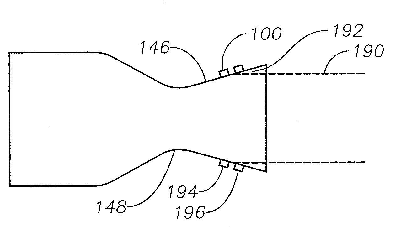
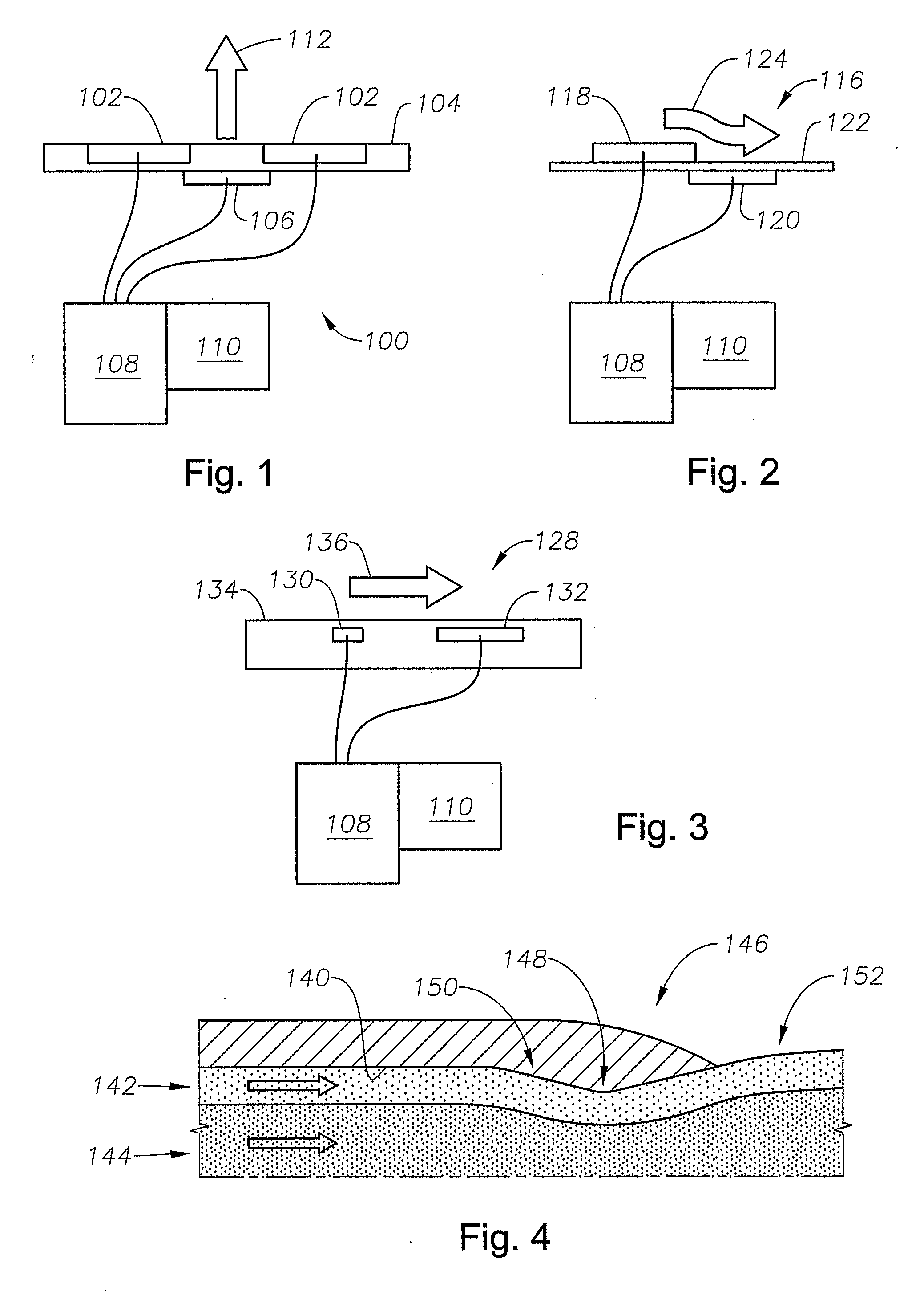
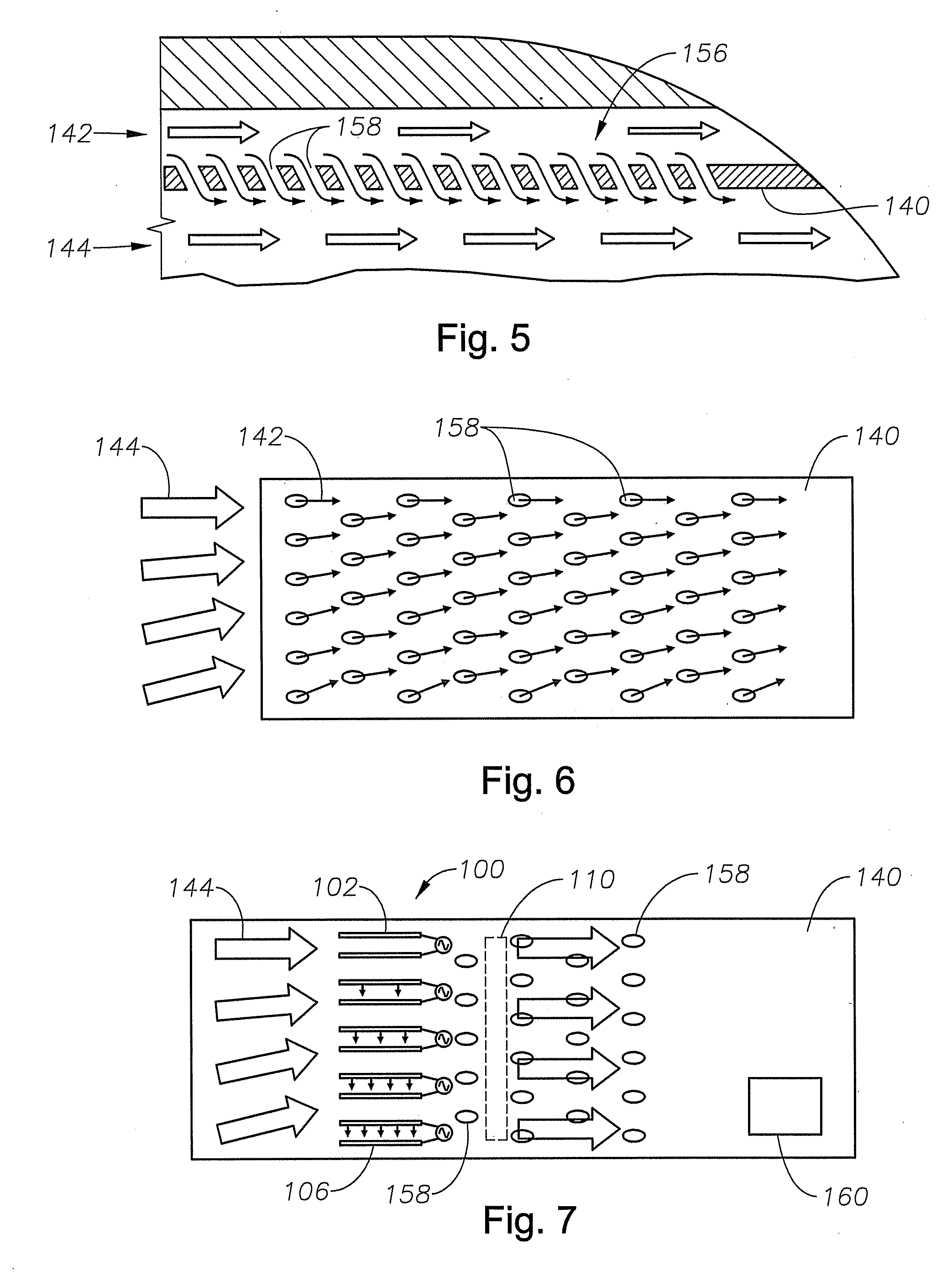
[0032]Referring to FIG. 1, solid state dielectric barrier discharge (“DBD”) plasma actuator 100 comprises surface electrode 102, dielectric barrier 104 and an electrode below the dielectric barrier, referred to as a buried electrode 106. In some embodiments, exposed electrodes 102 may be flush with dielectric barrier 104. In other embodiments, exposed electrodes 102 may protrude from dielectric barrier 104. An AC or pulsed power supply 108 is used to apply a voltage to the electrodes. A control module 110 may be used and may be a separate unit or it may be part of the power supply 108.

[0033]A jet of plasma is generated as ions move from surface electrode 102 toward buried electrode 106. These ions collide with neutral air molecules entraining additional flow. Two surface electrodes 102 may be located on either side of buried electrode 106. As the plasma flows from surface electrodes 102 toward buried electrode 106, the plasma jets may collide, causing plasma jet 112 to protrude norm...


PUM


Abstract

Dielectric barrier discharge plasma actuators are used to manipulate exhaust flow within and behind a jet engine nozzle. The dielectric barrier discharge plasma actuators may be used to direct cooling airflow near the surface of the nozzle to reduce heating of the nozzle, create thrust vectoring, and reduce noise associated with the exhaust flow exiting the nozzle.

Description

BACKGROUND[0001]1. Technical Field[0002]This disclosure relates in general to using plasma actuators to manipulate jet exhaust flow. This disclosure relates in particular to using dielectric barrier discharge plasma actuators on the surface of jet nozzles to improve nozzle thermal environment, reduce acoustic noise and increase propulsion system performance.[0003]2. Description of Related Art[0004]Jet engine exhaust nozzles must withstand severe thermal and acoustic effects. High temperatures and thermal gradients in the exhaust system reduce durability of nozzle materials and structures. High velocity exhaust flows, especially in the presence of dynamic flow separation and reattachment, result in severe jet noise. This can be an issue from the ground environment point of view (takeoff noise regulations, ground crew safety, etc) as well as having aircraft structural / acoustic implications. Thermal issues have traditionally been addressed by mixing cooler flow with hot flow or by intr...

Claims


Application Information

Patent Timeline
IPC IPC(8): F02K1/00F02K1/46
CPCF02K1/386F02K1/46F02K9/80F05D2250/324F05D2260/962F05D2250/323F05D2270/172
Inventor GINN, KERRY B.JENKINS, STEWART A.WELLS, DAVID M.MCCALLUM, BRENT N.
Owner LOCKHEED MARTIN CORP
Why Eureka
Try Eureka