Method of preparing cerium dioxide nanoparticles

a technology of cerium dioxide and nanoparticles, which is applied in the direction of metal/metal-oxide/metal-hydroxide catalysts, lanthanide oxides/hydroxides, chemical/physical processes, etc., can solve the problems of increasing engine wear, diesel engines often develop carbon deposits on the walls of cylinders, and incomplete combustion and exhaust smok

Active Publication Date: 2011-03-10
CERION
View PDF99 Cites 26 Cited by
  • Summary
  • Abstract
  • Description
  • Claims
  • Application Information

AI Technical Summary

Problems solved by technology

On the other hand, too high cetane fuels can result in incomplete combustion and exhaust smoke due to too brief of an ignition delay which does not allow proper mixing of the fuel and air.
During the normal course of operation, diesel engines often develop carbon deposits on the walls of their cylinders due to incomplete combustion of fuel.
These deposits can increase engine wear and, because of friction induced by the deposits, decrease engine efficiency.
Incomplete fuel combustion can also lead to the environmentally harmful emission of particulate materials, also referred to as soot.
The maintenance concentration is effective to maintain the catalytic iron oxide layer on the combustion surfaces but insufficient to decrease timing delay in the engine.
However, this method may accelerate the aging of the engine by formation of rust.
However, fuel additives of this type, in addition to using the rare and expensive metals such as platinum, can require several months before the engine is “conditioned”.
Vehicle on-board dosing systems that dispense cerium dioxide into the fuel before it enters the engine are known, but such systems are complicated and require extensive electronic control to feed the appropriate amount of additive to the fuel.
The resulting high water content can lead to a loss in engine power and lower fuel economy.
However, current methods do not allow the economical and facile preparation of cerium nanoparticles in a short period of time at very high suspension densities (greater than 0.5 molal, i.e., 9 wt %) that are sufficiently small in size (less than 8 nm in mean diameter), uniform in size frequency distribution (coefficient of variation [COV] of less than 15%, where COV is the standard deviation divided by the mean diameter), and stable for many desirable applications.
Cerium dioxide particles prepared using this type of mixing are often too large to be useful for certain applications.
Addition of reactants, such as cerium nitrate, an oxidant, and hydroxide ion, can result in the formation of nanoparticles.
This nucleation and growth process is not desirable if one wishes to limit the final size of the particles while still maintaining a high particle suspension density.
Such a batch reactor is not useful for producing a high yield (greater than 1 molal) of cerium dioxide nanoparticles that are very small, for example, less than 10 nm in a reasonably short reaction time (for example, less than 60 minutes).
Colloid mills are not useful for reducing the particle size of large cerium dioxide particles because the particles are too hard to be sheared by the mill in a reasonable amount of time.
This is a time consuming, expensive process that invariably produces a wide distribution of particle sizes.
Most stabilizers used to prevent agglomeration in an aqueous environment are ill suited to the task of stabilization in a nonpolar environment.
When placed in a nonpolar solvent, such particles tend to immediately agglomerate and, consequently, lose some, if not all, of their desirable nanoparticulate properties.
Changing stabilizers can involve a difficult displacement reaction or separate, tedious isolation-redispersal methods (for example, precipitation and subsequent redispersal with the new stabilizer using ball milling).
As there was no attendant measurement of engine power, the claimed 85-90% reductions in particulate emissions may have been an artifact of the loss of engine power and thus been an unacceptable trade-off of power for emissions reduction.
These types of fuel additives also have a long conditioning period.

Method used


Image

  • Method of preparing cerium dioxide nanoparticles
  • Method of preparing cerium dioxide nanoparticles
  • Method of preparing cerium dioxide nanoparticles

Examples


example 1

Preparation of Cerium Dioxide Nanoparticles: Single Jet Addition

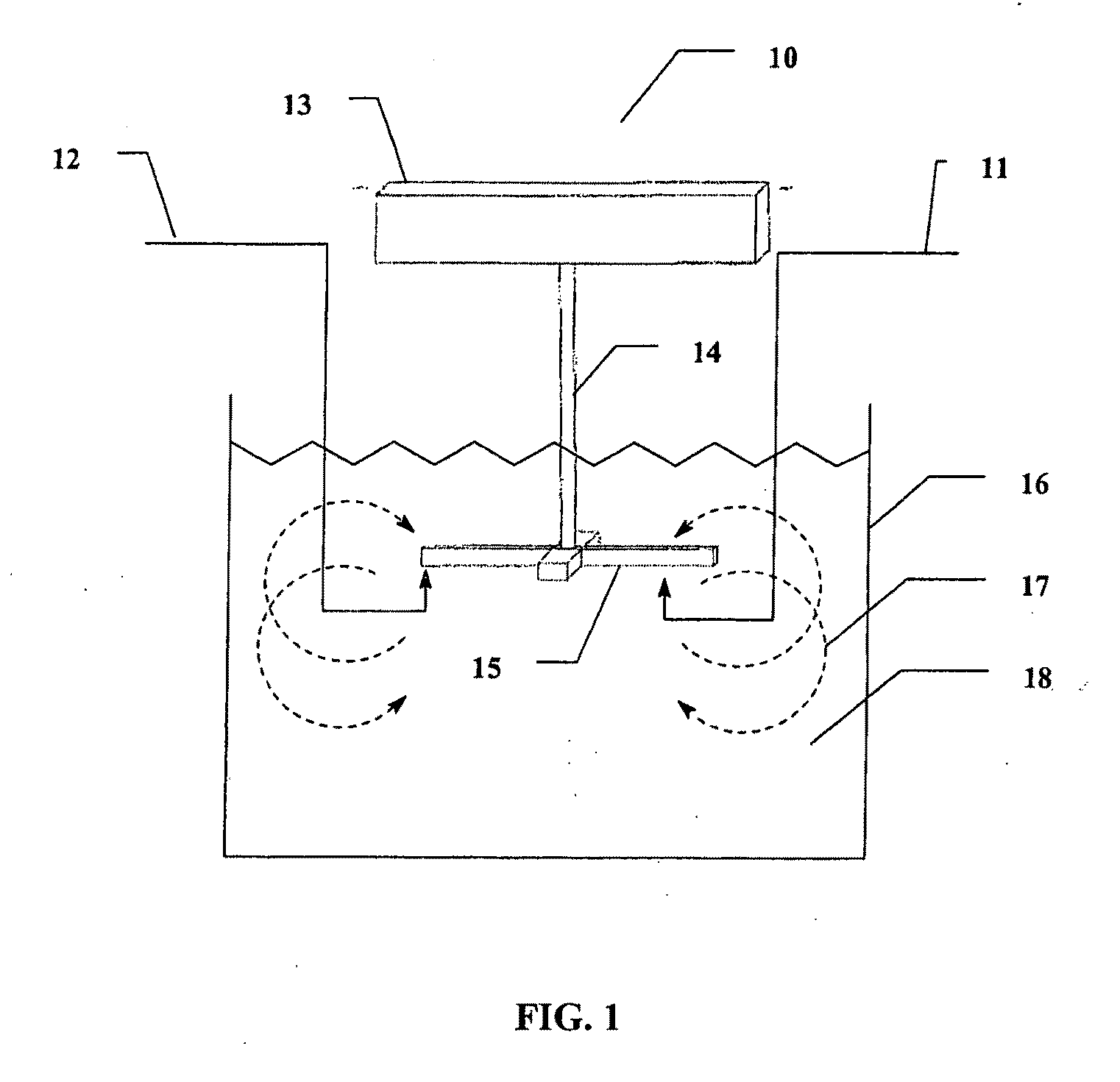
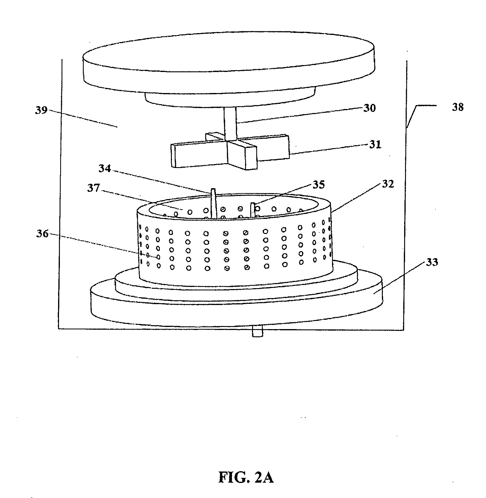
[0236]To a 3 liter round bottom stainless steel reactor vessel was added 1.267 liters of distilled water, followed by 100 ml of Ce(NO3)3.6H2O solution (600 gm / liter Ce(NO3)3.6H2O). The solution was clear and has a pH of 4.2 at 20° C. Subsequently, 30.5 gm of 2-[2-(2-methoxyethoxy)ethoxy]acetic acid (MESA) was added to the reactor vessel. The solution remained clear, and the pH was 2.8 at 20° C. A high sheer mixer was lowered into the reactor vessel, and the mixer head was positioned slightly above the bottom of the reactor vessel. The mixer was a colloid mill manufactured by Silverson Machines, Inc., modified to enable reactants to be introduced directly into the mixer blades by way of a peristaltic tubing pump. The mixer was set to 5,000 rpm, and 8.0 gm of 30% H2O2 was added to the reactor vessel. Then 16 ml of 28%-30% NH4OH, diluted to 40 ml, was pumped into the reactor vessel by way of the mixer head in about 12 seco...

examples 1a-f

Evaluation of Alternative Stabilizers to MEEA

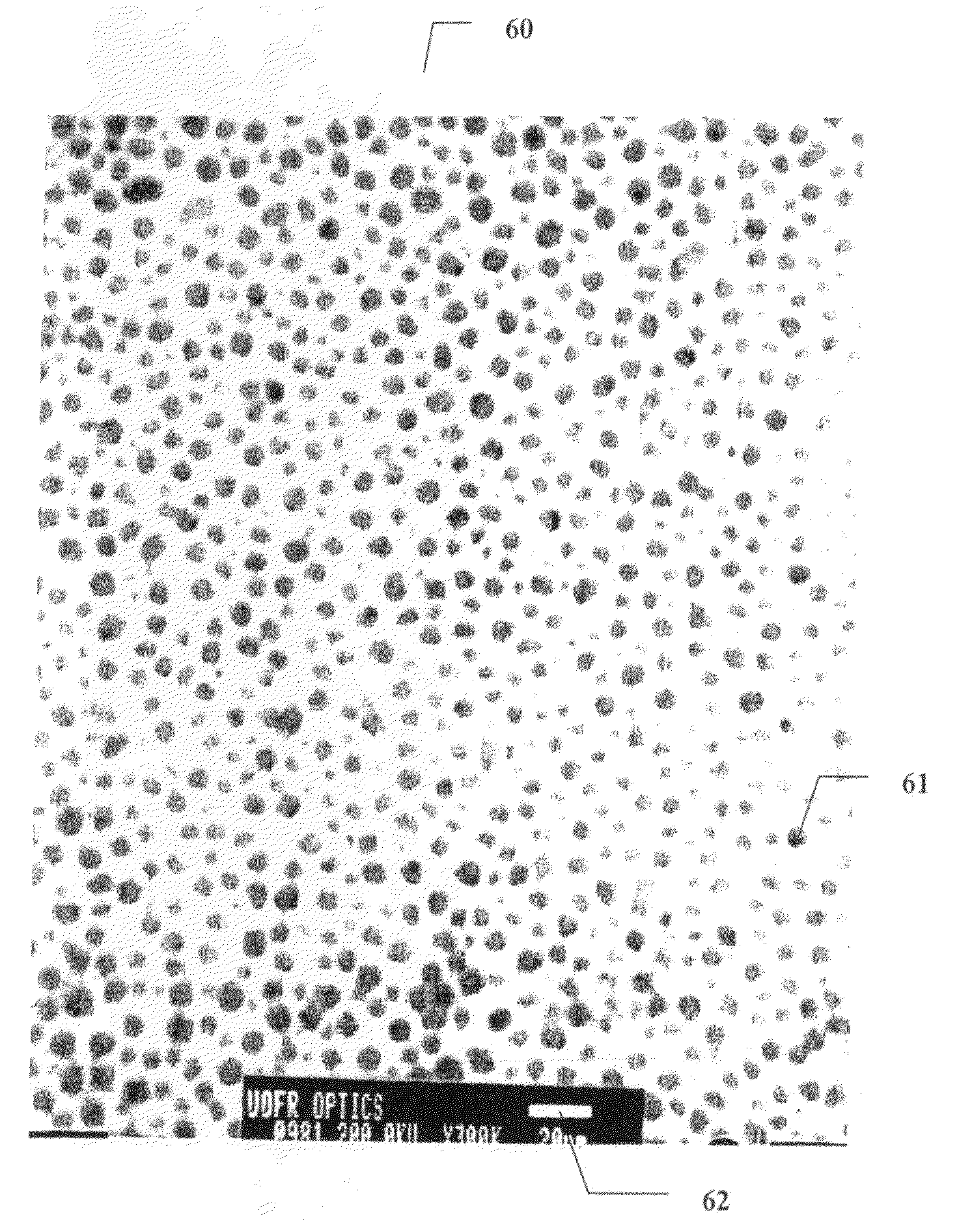
[0240]Example 1 was repeated, except that in Example 1a an equivalent molar amount of succinic acid was substituted for the MEEA stabilizer. A brown precipitate that readily settled was obtained, which is an indication of very large particles (several tens of microns). The same experiment was repeated each time substituting an alternative stabilizer (malonic acid—Example 1b, glycerol—Example 1c, ethyl acetoacetate—Example 1d). In each case, a readily settling brown precipitate was obtained, indicating the failure to obtain nanoparticles. For Example 1e, lactic acid at twice the molar concentration was substituted for the MEEA stabilizer. Quasi-inelastic dynamic light scattering measurements revealed a mean hydrodynamic diameter particle size of 5.4 nm when the hydroxide was doubled, and 5.7 nm when the hydroxide was increased by 75%. Mixtures of EDTA (which by itself produces no particles) and lactic acid at a ratio of about 20% / 80% also ...

example 2

CeO2 Precipitation with EDTA / Lactic Acid Stabilizer—Effect of Mixing

[0241]To a 3 liter round bottom stainless steel reactor vessel was added 76.44 gm EDTA disodium salt in distilled water to a total weight of 1000 gm, 74.04 gm of DL-lactic Acid (85%), 240.0 gm of Ce(NO3)3.6H2O in 220 gm of distilled water and 19.2 gm of 50% H2O2 aqueous solution. As in Example 1, the mixer speed was set to 5000 rpm, and the contents of the reactor were brought to a temperature of 22° C. Separately, a solution of 128.0 gm NH4OH (28-30%) was prepared. This quantity of hydroxide is equivalent to twice the number of moles of cerium solution, so the initially nucleated precipitate was presumably the bis-hydroxyl intermediate. In one experiment, the ammonium hydroxide solution was single jetted into the reactor in the reaction zone defined by the mixer blades and perforated screen. In another experiment, the hydroxide was added via a single jet just subsurface into the reactor in a position remote from th...


PUM

PropertyMeasurementUnit
temperatureaaaaaaaaaa
molar ratioaaaaaaaaaa

Abstract

A method of making cerium dioxide nanoparticles includes: a) providing an aqueous reaction mixture having a source of cerous ion, a source of hydroxide ion, a nanoparticle stabilizer, and an oxidant at an initial temperature no higher than about 20° C.; b) mechanically shearing the mixture and causing it to pass through a perforated screen, thereby forming a suspension of cerium hydroxide nanoparticles; and c) raising the initial temperature to achieve oxidation of cerous ion to eerie ion and thereby form cerium dioxide nanoparticles having a mean diameter in the range of about 1 nm to about 15 nm. The cerium dioxide nanoparticles may be formed in a continuous process.

Description

CROSS-REFERENCE TO RELATED APPLICATIONS[0001]This application claims the benefit of priority from: U.S. Provisional Application Ser. No. 60 / 824,514, CERIUM-CONTAINING FUEL ADDITIVE, filed Sep. 5, 2006; U.S. Provisional Application Ser. No. 60 / 911,159, REVERSE MICELLAR FUEL ADDITIVE COMPOSITION, filed Apr. 11, 2007; and U.S. Provisional Application Ser. No. 60 / 938,314, REVERSE MICELLAR FUEL ADDITIVE COMPOSITION, filed May 16, 2007, the disclosures of which are incorporated herein by reference.FIELD OF THE INVENTION[0002]The present invention relates to cerium dioxide particles and, in particular, to a method for the preparation of cerium dioxide nanoparticles that may be used as components of fuel additive compositions.BACKGROUND OF THE INVENTION[0003]Diesel fuel ranks second only to gasoline as a fuel for internal combustion engines. Trucks, buses, tractors, locomotives, ships, power generators, etc. are examples of devices that use diesel fuel. Passenger cars and sport utility vehi...

Claims


Application Information

Patent Timeline
Patent Type & Authority Applications(United States)
IPC IPC(8): C10L1/188C01F17/00C10L1/12C09K3/14B01F23/00B82Y40/00C01F17/235C09K23/00
CPCB01F3/0807Y02T50/678B01J13/0047B01J13/0086B82Y30/00C10L1/10C10L1/103C10L1/1233C10L1/125C10L1/1258C10L1/1608C10L1/1616C10L1/1811C10L1/1824C10L1/1881C10L1/1883C10L1/19C10L1/1985C10L1/2222C10L1/2437C10L10/02C10L10/08C10L10/12C10M2201/062C10N2230/06C10N2240/10B01F7/164B01J23/10C10N2210/03C10N2220/082C01P2002/72C01P2004/04C01P2004/52C01P2004/64C10N2030/06C10N2040/25C01F17/235B01F23/41B01F27/812C10N2010/06C10N2020/06
Inventor DIFRANCESCO, ALBERT GARYHAILSTONE, RICHARD K.LANGNER, ANDREASREED, KENNETH J.
Owner CERION
Why Eureka
Try Eureka