
Nano-fibered membrane for western blot and manufacturing method of the same

a technology of nanofibers and western blots, applied in the direction of membranes, instruments, electric/magnetic/electromagnetic heating, etc., can solve the problems of high cost of porous membrane manufacturing, difficult to manufacture in a large amount, uneven distribution of pore structures, etc., and achieve excellent sensitivity and maximum surface area

Active Publication Date: 2011-03-31
AMOLIFESCI CO LTD
View PDF11 Cites 14 Cited by
  • Summary
  • Abstract
  • Description
  • Claims
  • Application Information

AI Technical Summary

Benefits of technology

[0014]Therefore, it is an object of the present invention to provide a membrane for Western blotting which is manufactured using an electrospinning process, consists of a nanofiber web having maximized surface area so as to allows the need for a methanol pretreatment process to be eliminated, and thus has excellent sensitivity without a background, and a method for manufacturing the same.

Problems solved by technology

At this time, the SDS molecular sieve interferes with the movement of the proteins, so that small molecules move fast, and large molecules move slowly, thus forming bands of various sizes.
However, the porous membrane is manufactured at a high cost and difficult to manufacture in a large amount.
Also, if the porous membrane is manufactured by phase separation, there is a disadvantage in that the distribution of pore structures is not uniform.
If this hydrophilizing process is not performed, the sensitivity of the membrane can be reduced, because proteins are not sufficiently adsorbed on the membrane.
This methanol pretreatment process can greatly reduce the strength of the membrane to cause cracks and forms air bubbles to cause a background, thus making it difficult to precisely detect a desired protein.

Method used


Image

  • Nano-fibered membrane for western blot and manufacturing method of the same
  • Nano-fibered membrane for western blot and manufacturing method of the same
  • Nano-fibered membrane for western blot and manufacturing method of the same

Examples


example 1

[0059]The hydrophobic homopolymer PVdF (HSV 900) was dissolved in the solvent DMAc in an amount of 20 wt % relative to the total weight of the solution, thereby preparing a spinning solution. The spinning solution was transferred to a spinneret nozzle using a metering pump, and then electrospun under the following conditions, thereby obtaining a PVdF nanofiber web: voltage applied: 25 kV; the interval between the spinneret and the current collector: 20 cm; amount discharged per minute: 0.005 cc / g·hole / min; room temperature and atmospheric pressure.

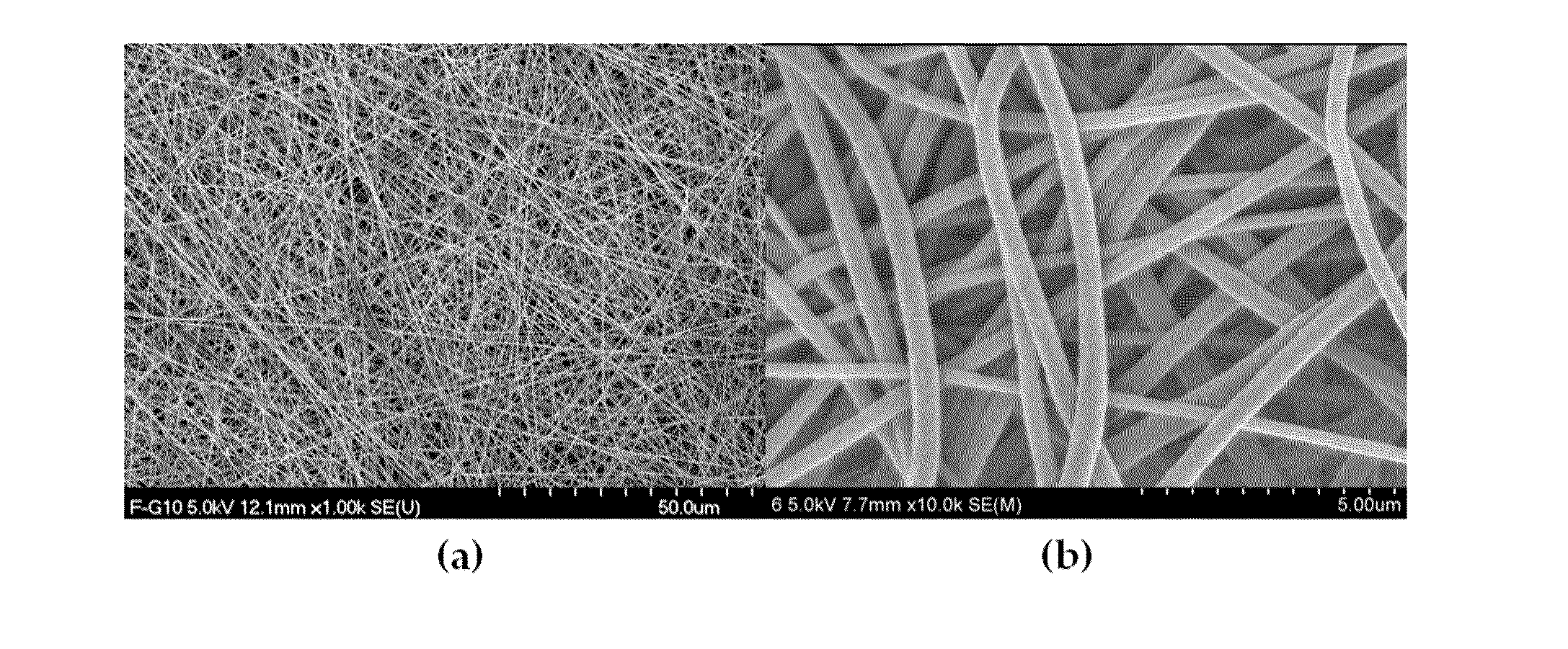
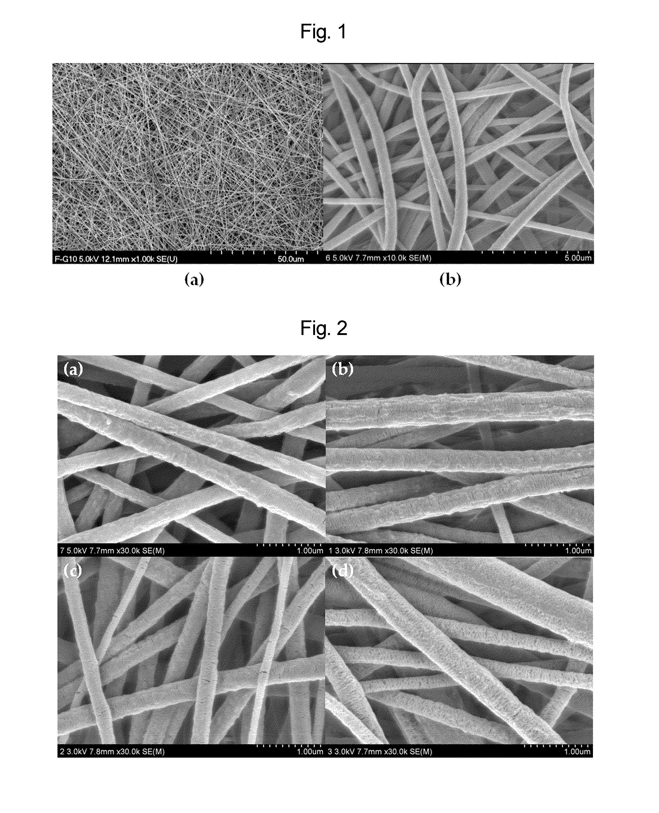
[0060]FIG. 1 is a scanning electron micrograph of the spun PVdF nanofiber web. As shown in FIG. 1, the spun nanofibers had an average fiber diameter of about 300-400 nm. Also, the nanofibers had a relatively uniform pore diameter and a three-dimensional open pore structure.

[0061]The spun PVdF nanofiber web was calendered by passing it through a hot-plate roll heated to 140° C., thereby manufacturing a PVdF nanofiber membrane. The membrane ...

examples 2 and 3

[0062]In Examples 2 and 3, the hydrophobic homopolymer PVdF (761) alone (Example 2) or a 50:50 (w / w) mixture of the homopolymer PVdF (761) and the copolymer PVdF (2801) (Example 3) was electrospun in the same manner as Example 1, followed by calendering, thereby obtaining nanofiber membranes. The membranes manufactured in Examples 2 and 3 were subjected to TGA, XRD, SEM and DSC analysis for comparison with a membrane manufactured in Comparative Example. In the results of thermogravimetric analysis (TGA), the samples manufactured in Comparative Example and Examples showed substantially the same results and showed the typical characteristics of the PVdF polymer. These results are described below in the section “structural analysis of the membranes”.

example 4

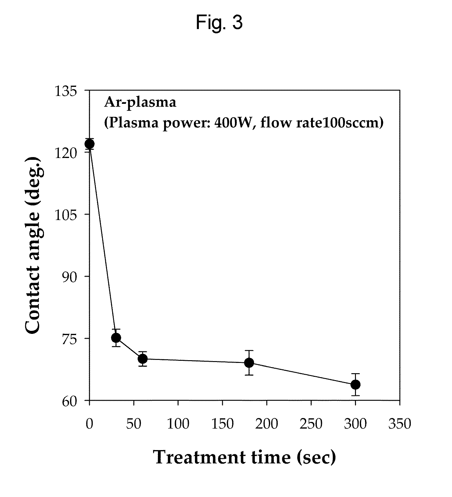
[0063]In Example 4, the PVdF nanofiber membrane manufactured in Example 1 was subjected to surface modification using a plasma cleaner system. The surface modification was carried out for each of 30, 60, 150 and 300 sec at 400 W while supplying 100 sccm of argon.

[0064]FIG. 2 is a set of scanning electron micrographs showing the surface structure of the plasma-treated PVdF membrane of Example 4 according to plasma treatment time. As can be seen in FIG. 2, as the plasma treatment time increased, the size of cracks that occurred on the surface of the PVdF nanofibers increased. This is believed to be because the nanofiber surface was etched due to the plasma treatment.

[0065]FIG. 3 shows the water contact angle of the plasma-treated PVdF membrane of Example 4 according to plasma treatment time. As can be seen in FIG. 3, the water contact angle of the PVdF membrane was decreased due to the plasma treatment. Namely, the membrane showed a hydrophilic nature due to the plasma treatment. As t...


PUM

PropertyMeasurementUnit
diameteraaaaaaaaaa
temperatureaaaaaaaaaa

Abstract

The present invention relates to a membrane for Western blotting which has a three-dimensional open pore structure, an average pore diameter of 0.1-1.0 μm and a thickness of 30-200 μm, wherein the membrane for Western blotting is manufactured by subjecting nanofibers having an average fiber diameter of 50-1000 nm, obtained by electrospinning, to a hot-plate calendering process, and a method for manufacturing the same. The method comprises the steps of: dissolving a hydrophobic material in a solvent to prepare a spinning solution; subjecting the spinning solution to a spinning process to obtain a hydrophobic polymer nanofiber web; and calendering the obtained nanofiber web to obtain a membrane for Western blotting.

Description

BACKGROUND OF THE INVENTION[0001]1. Field of the Invention[0002]The present invention relates to a membrane for Western blotting which has a three-dimensional open pore structure, an average pore diameter of 0.1-1.0 μm and a thickness of 30-200 μm, wherein the membrane for Western blotting is manufactured by subjecting nanofibers having an average fiber diameter of 50-1000 nm, obtained by electrospinning, to a hot-plate calendering process, and a method for manufacturing the same.[0003]2. Description of the Prior Art[0004]Membranes for Western blotting which are currently commonly used include porous membranes made of nitrocellulose (NC), nylon or polyvinylidene fluoride (hereinafter referred to as “PVdF”) polymers.[0005]Particularly, PVdF-based membranes are mainly used as membranes for Western blotting, because they have excellent protein-binding sensitivity, membrane strength and handling properties compared to nitrocellulose- or nylon-based membranes.[0006]Western blotting is a ...

Claims


Application Information

Patent Timeline
Patent Type & Authority Applications(United States)
IPC IPC(8): G01N33/50B32B38/00B29C47/08
CPCB01D67/002B01D67/009B01D2323/39G01N27/44739D01D5/0007Y10T442/277
Inventor KOOK, JOONG KICHO, KI WOONKIM, CHANSUH, SANG CHULKIM, CHEOL HYEONSEO, IN YONGLEE, SEUNG HOONKIM, YUN HYEPARK, JU YOUNG
Owner AMOLIFESCI CO LTD
Learn More