
Method and apparatus for reduction of contaminants in evaporator distillate

a technology of evaporator distillate and contaminants, which is applied in the direction of lighting and heating apparatus, liquid degasification, separation processes, etc., can solve the problems of increasing anion exchange equipment operational costs, or both

Active Publication Date: 2011-04-07
BL TECH INC
View PDF7 Cites 11 Cited by
  • Summary
  • Abstract
  • Description
  • Claims
  • Application Information

AI Technical Summary

Benefits of technology

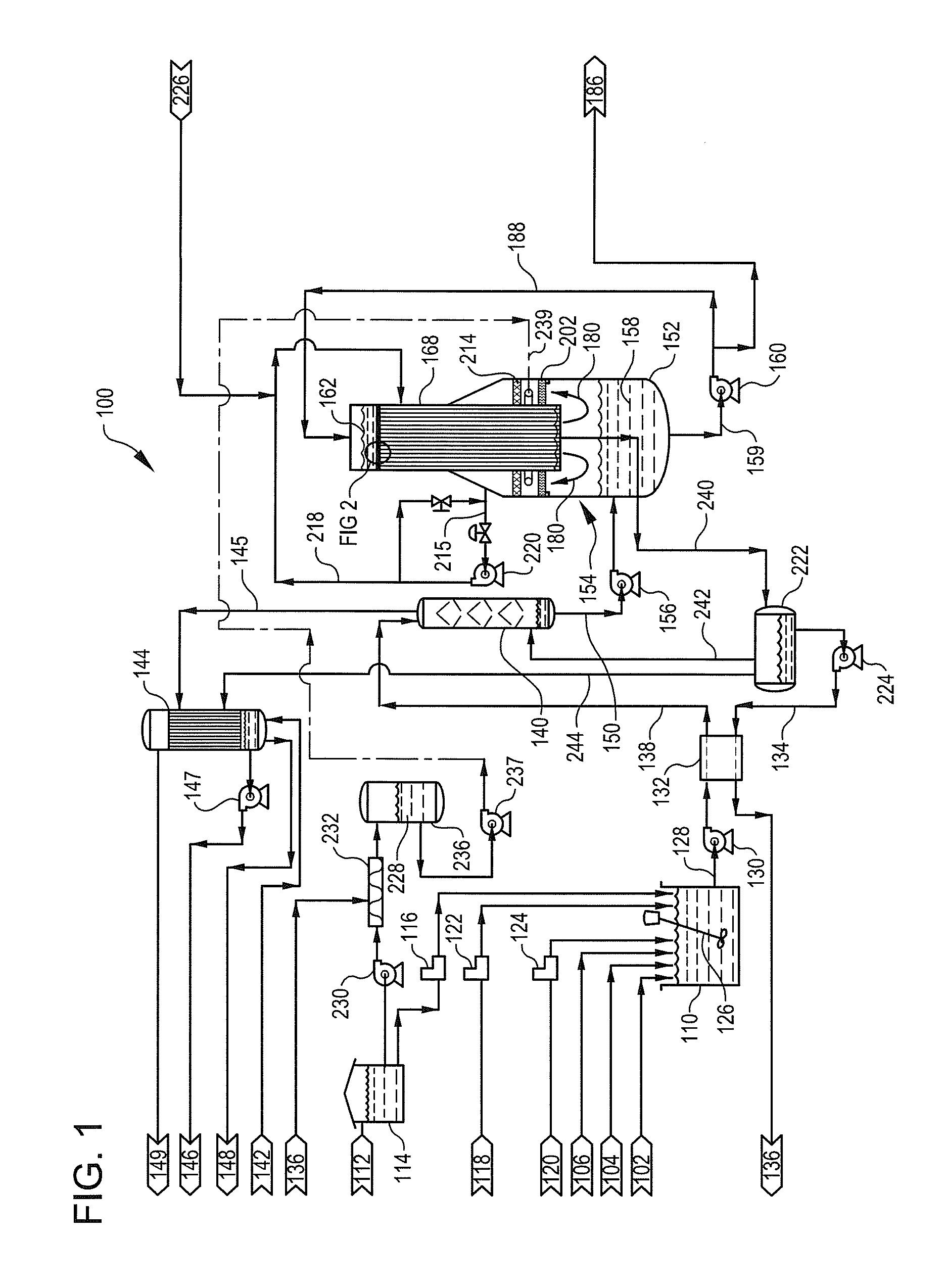
The patent describes a process and apparatus for producing high purity distillate from a feedwater stream that contains water and volatile silica, as well as other organic compounds. The process involves using a vertical tube, falling film evaporator system to evaporate the feedwater and generate a contaminated steam stream with entrained water droplets, volatile silica compounds, and volatile organic compounds. A caustic mixing system is used to mix concentrated caustic with water to provide a dilute caustic solution, which is then fed to a contamination reduction system to remove the volatile silica and organic compounds. The process produces a high purity water vapor stream that is suitable for further purification and utilization.

Problems solved by technology

Increased silica levels generally require increased steam generator blowdown rates, or result in increased operational costs of anion exchange equipment, or both.
A problem arises since silica molecules (SiO2) have a small vapor pressure in the normal operating temperature range of wastewater treatment evaporators.

Method used


Image

  • Method and apparatus for reduction of contaminants in evaporator distillate
  • Method and apparatus for reduction of contaminants in evaporator distillate
  • Method and apparatus for reduction of contaminants in evaporator distillate

Examples


Embodiment Construction

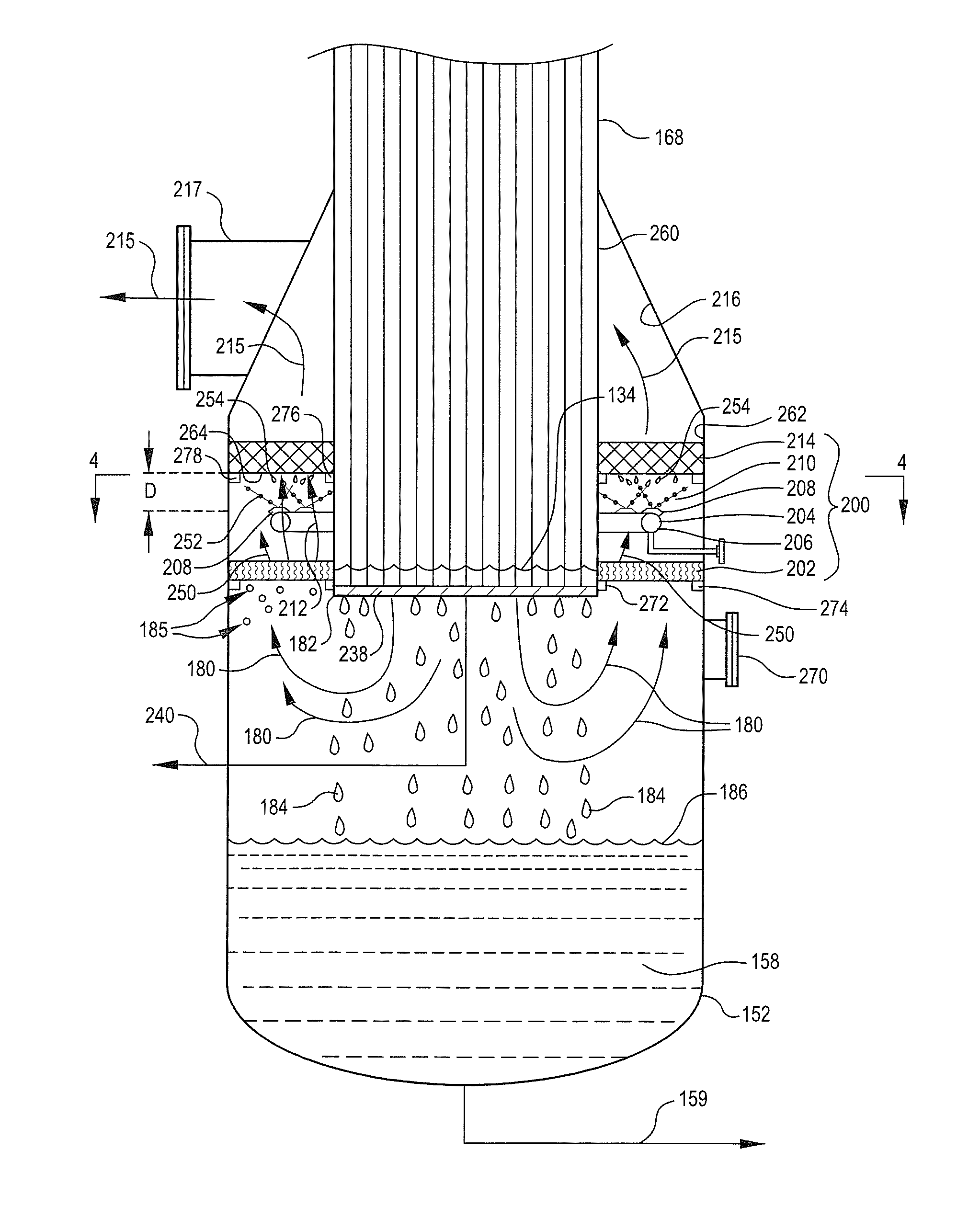
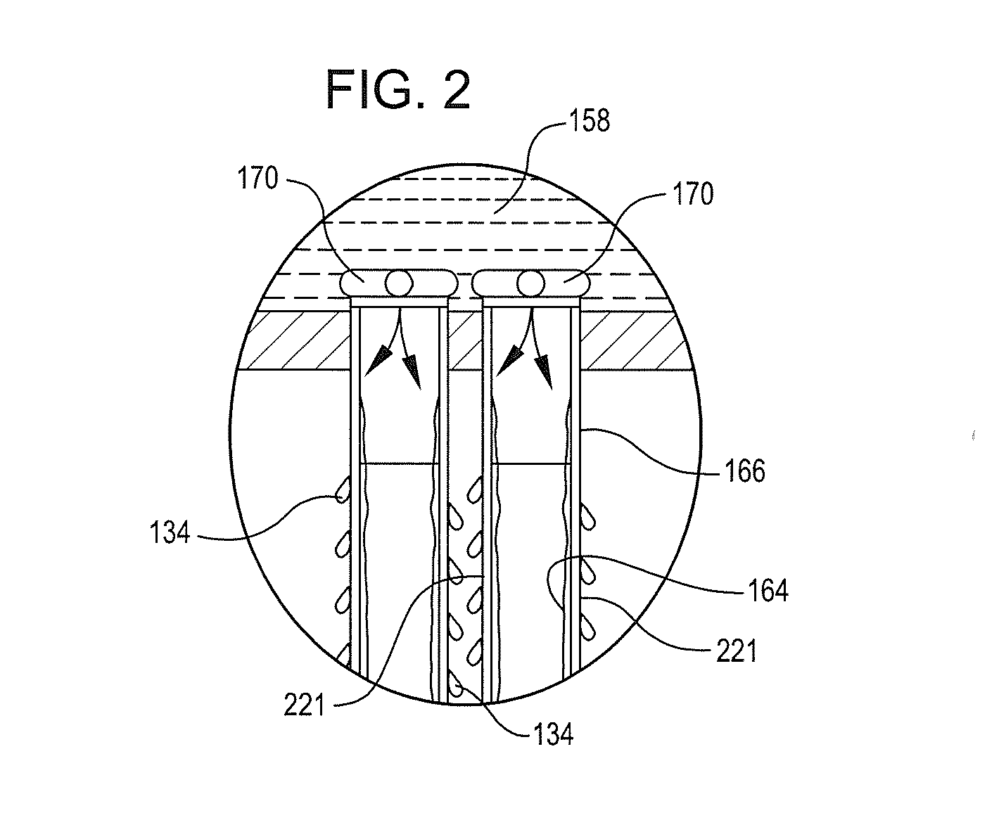
[0017]Attention is directed to FIG. 1, which provides a flow schematic detailing a vertical tube, falling film, mechanical vapor compression evaporator system 100, which is one useful evaporator design in which the apparatus and method for reduction of contaminants in evaporator distillate, to which this specification is directed, may be effectively employed. As depicted in such an embodiment, the evaporator system 100 is shown as configured for use in treating produced water from hydrocarbon production operations, such as the recovery of heavy oil from tar sands. Produced water 102, any makeup water 104, and optionally blowdown 106 from steam generators (not shown) is collected and delivered to an evaporator feed tank 110. Caustic 112 (such as sodium hydroxide) is provided to caustic tank 114. Caustic 112 may be provided (as required by process conditions) by caustic pump 116 to evaporator feed tank 110. Optionally, scale inhibitors 118 and / or antifoam 120 may be added via pumps 12...


PUM

PropertyMeasurementUnit
heightaaaaaaaaaa
heightaaaaaaaaaa
distanceaaaaaaaaaa

Abstract

Method and apparatus for producing high purity distillate in evaporators. The method and apparatus is useful for evaporation of waters where volatile silica compounds are encountered, and in cases where volatile organic compounds are encountered, such as in production of hydrocarbons from geological formations. An evaporator having a contaminant reduction system is provided. The contaminant reduction system includes an upflow first mist eliminator portion to remove entrained liquid droplets and produce an intermediate purity water vapor stream. A continuous spray system provides a spray of dilute caustic solution in a selected spray configuration for mass transfer contact with the passing intermediate purity water vapor stream, to remove volatile silica compounds therefrom, and produce a partially decontaminated steam stream having mist particles therein. An upflow second mist eliminator portion is provided to remove the residual mist particles, and produce a high purity water vapor stream. The high purity water vapor stream may be first compressed, but in any event is condensed to provide a high purity distillate stream.

Description

CROSS REFERENCE TO RELATED APPLICATION[0001]The present application claims priority benefit under 35 USC §119 of U.S. Provisional Patent Application Ser. No. 61 / 278,376 filed Oct. 5, 2009.TECHNICAL FIELD[0002]The method and apparatus disclosed and claimed herein relates to treatment of waters containing solutes in evaporation equipment. More specifically, the method and apparatus disclosed herein relates to techniques for efficiently and reliably generating distillate in evaporation equipment that is substantially free from undesirable solutes.BACKGROUND OF THE INVENTION[0003]Evaporation of waters containing various solutes has become routine in many industrial operations. For example, evaporative based water treatment systems are now widely used for treatment of cooling tower blowdown, whether in electric power generation operations or in other industrial facilities. Also, the treatment of produced waters in oil and gas production, including production of oil from tar sands or othe...

Claims


Application Information

Patent Timeline
Patent Type & Authority Applications(United States)
IPC IPC(8): B01D3/38
CPCB01D1/065B01D1/28B01D1/2896B01D1/305C02F1/048B01D19/0047C02F1/08B01D3/008B01D5/006
Inventor HEINS, WILLIAM F.WILSON, GREGG L.
Owner BL TECH INC
Learn More