Hydrogen product method and apparatus

a technology of hydrogen products and methods, applied in the direction of liquid-gas reaction processes, chemistry apparatus and processes, hydrogen separation using solid contact, etc., can solve the problems of high oxygen consumption required for such conversion, and unacceptably high production costs, so as to increase the production rate and increase the hydrogen containing product

Inactive Publication Date: 2011-04-14
PRAXAIR TECH INC
View PDF7 Cites 45 Cited by
  • Summary
  • Abstract
  • Description
  • Claims
  • Application Information

AI Technical Summary

Benefits of technology

[0011]The downstream unit operation can be a hydrogen pressure swing adsorption unit. In such case, the shifted stream is cooled and the hydrogen is separated from the shifted stream within the hydrogen pressure swing adsorption unit to produce a hydrogen stream containing the hydrogen as the hydrogen containing product and a tail gas stream. The tail gas stream is utilized as part of a fuel fed to burners firing into a furnace section of the steam methane reformer at a tail gas flow rate of the tail gas stream that is greater than before the retrofit of the catalytic reactor to decrease consumption of a remaining part of the fuel.
[0012]As can be appreciated, by limiting the temperature of the catalytic reactor to 870° C., the amount of oxygen will be reduced over that required had the reactor been operated at a higher temperature so that all of the hydrocarbons contained in the feed were reacted with no methane slip. Additionally, since more hydrocarbons are being reacted in both the steam methane reformer and the catalytic reactor more synthesis gas will be produced for use in the downstream operation to increase production of the hydrogen containing product. This is particularly advantageous when the downstream operation is a hydrogen pressure swing adsorption unit because not only will more hydrogen be produced, to in turn increase hydrogen production, but also, more tail gas will be produced as a result of the hydrogen being separated from the shifted stream. Typically, the fuel supplied to burners firing into the furnace section is a combination of natural gas and tail gas. The increased production of the tail gas will decrease the requirements for the natural gas and therefore, make the retrofit even more attractive from a financial standpoint
[0013]A feed gas stream containing hydrocarbons and sulfur species can be treated by passing the feed gas stream through a hydrotreater of the existing hydrogen plant to hydrogenate the sulfur species to hydrogen sulfide and then through an adsorbent bed of the existing hydrogen plant to adsorb the hydrogen sulfide, thereby to form a treated feed gas stream. The treated feed gas stream is divided into the first hydrocarbon containing feed gas stream and the second hydrocarbon containing feed gas stream and the flow rate of the feed gas stream after the retrofit of the catalytic reactor is increased.
[0016]A catalytic reactor, provided as a retrofit to the existing hydrogen plant, is configured to react a second hydrocarbon containing feed gas stream with oxygen and a further part of the steam to produce a second synthesis gas stream. The second synthesis gas stream has a methane slip of at least about 2.0 dry mol percent, a hydrogen to carbon monoxide ratio of at least about 4.0 on a molar basis and a temperature of no greater than about 870° C. The at least one water-gas shift reactor is in flow communication with both the catalytic reactor and the steam methane reformer such that that the second synthesis gas stream combines with the first synthesis gas stream to produce a combined stream fed into the at least one water-gas shift reactor. At least one boiler is positioned between the catalytic reactor and water-gas shift reactor such that the combined stream is at a temperature suitable for entry into the at least one water-gas shift reactor. A production apparatus is provided in flow communication with the at least one water-gas shift reactor that utilizes synthesis gas in the shifted stream to produce the hydrogen containing product. As a result, an amount of the available synthesis gas provided in the shifted stream to the production apparatus is increased by virtue of combination of the second synthesis gas stream with the first synthesis gas stream such that production of the hydrogen containing product is increased.
[0017]The production apparatus can be a hydrogen pressure swing adsorption unit configured to separate the hydrogen from the shifted stream to produce a hydrogen product stream as the hydrogen containing product and a tail gas stream. The hydrogen pressure swing adsorption unit is connected to burners firing into a furnace section of the steam methane reformer such that the tail gas stream is fed as part of a fuel to burners. The existing hydrogen plant with the catalytic reactor is configured to operate such that the pressure swing adsorption unit produces the hydrogen product stream and the tail gas stream at increased production rates over the existing hydrogen plant due to the combination of the second synthesis gas stream with the first synthesis gas stream and consumption of a remaining part of the fuel fed to the burners decreases due to increased production of the tail gas stream.

Problems solved by technology

The problem with this is that for the production of hydrogen, the use of such an autothermal reformer is not a particularly cost effective way of increasing the production of hydrogen given that the expense of the oxygen comes into play resulting in unacceptably high production costs.
However, where hydrogen is to be produced, it is not desirable to thus add more nitrogen to the synthesis gas given that the same will have to be separated from the synthesis gas in a pressure swing adsorption unit.
Consequently, the use of a higher purity oxygen containing stream even in this patent is not a particularly cost effective integration given that in autothermal reformering, typically, the reformer is operated so as to produce as complete a methane conversion as possible and the oxygen consumption required for such conversion represents an unacceptable high cost.
This high cost of oxygen makes the addition of an autothermal reformer to a hydrogen plant impractical.

Method used


Image

  • Hydrogen product method and apparatus
  • Hydrogen product method and apparatus

Examples


Embodiment Construction

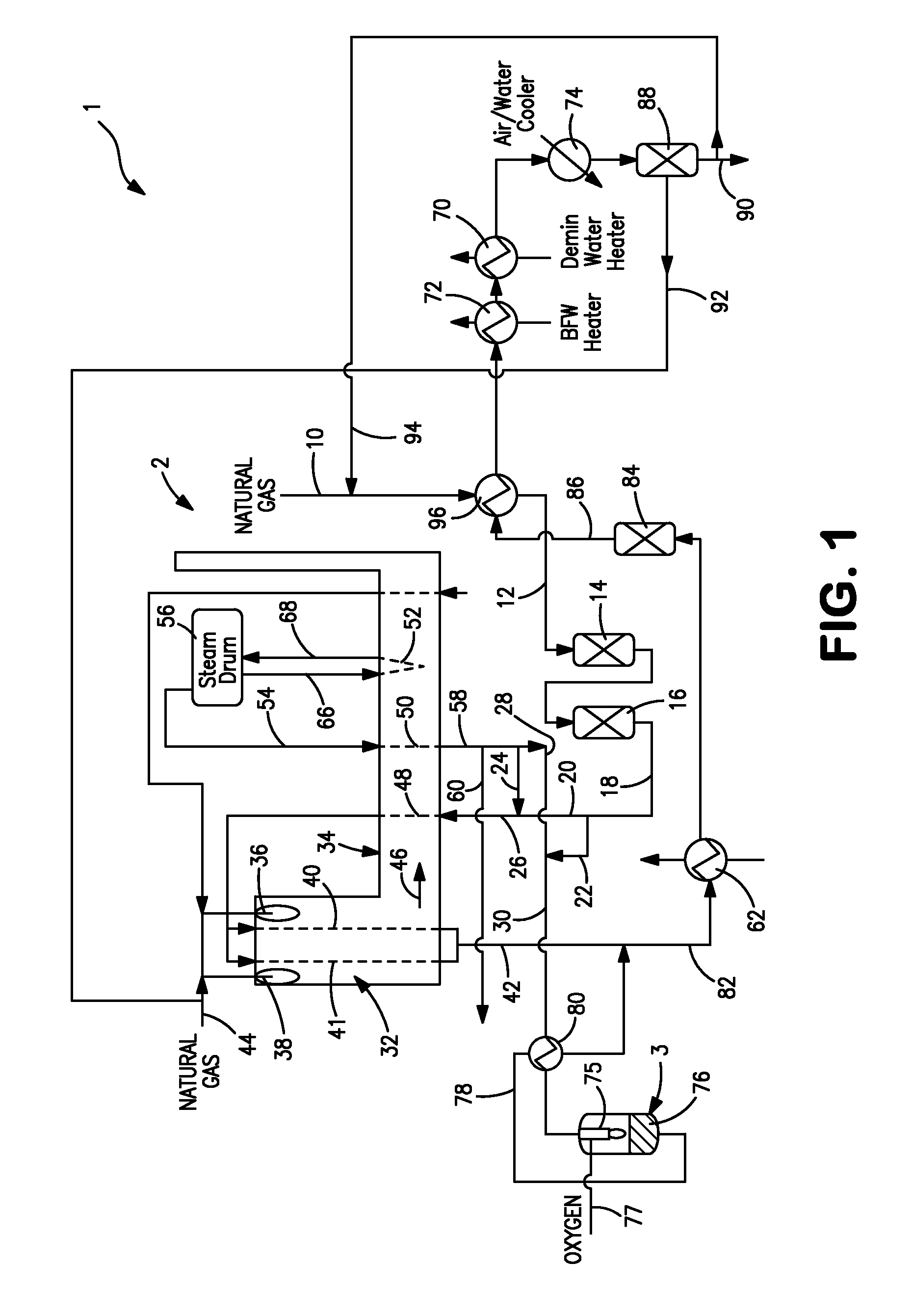
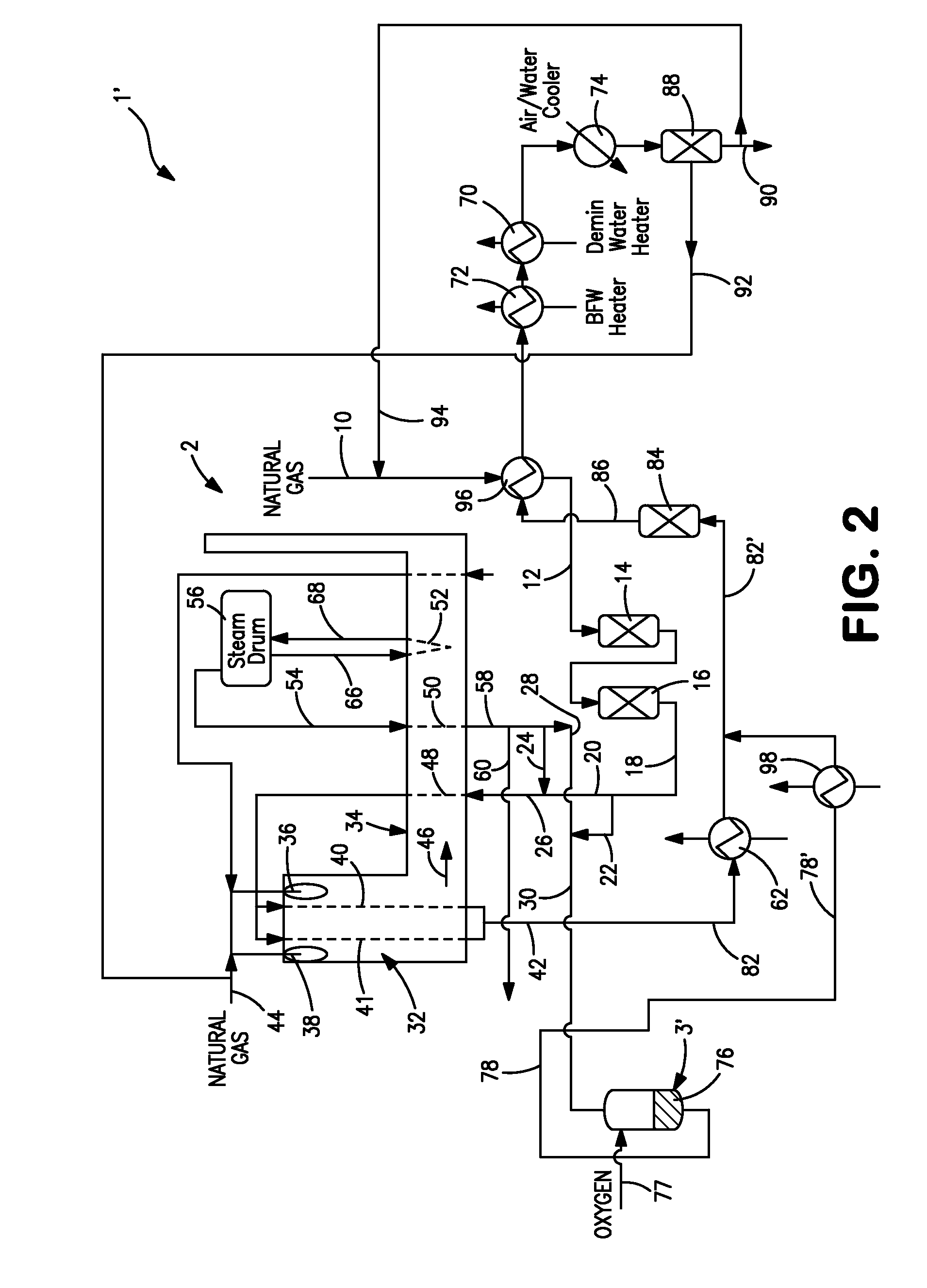
[0025]With reference to FIG. 1, a hydrogen plant 1 in accordance with the present invention is illustrated. Hydrogen plant 1 has a steam methane reformer 2 incorporating a steam generation system and a catalytic reactor 3 that has been retrofitted to the hydrogen plant 1 in order to increase its output of hydrogen. Hydrogen plant 1 is designed to reform a natural gas stream 10. However, this is simply for purposes of illustration in that hydrogen plant 1 could be designed to process any other type of hydrocarbon containing stream such as naphtha or other type of feed containing hydrocarbons. Furthermore, although the present invention is illustrated in connection with a hydrogen plant having a pressure swing adsorption unit 88 to be discussed, the present invention has broader application. For example, a shifted stream 86, also to be discussed, could be used in other types of unit operation or production apparatus such as an amine unit to remove carbon dioxide and then form a hydrog...


PUM

PropertyMeasurementUnit
temperatureaaaaaaaaaa
temperaturesaaaaaaaaaa

Abstract

A method and apparatus for producing a hydrogen containing product in which hydrocarbon containing feed gas streams are reacted in a steam methane reformer of an existing hydrogen plant and a catalytic reactor that reacts hydrocarbons, oxygen and steam. The catalytic reactor is a retrofit to the existing hydrogen plant to increase hydrogen production. The resulting synthesis gas streams are combined, cooled, subjected to water-gas shift and then introduced into a production apparatus that can be a pressure swing adsorption unit. The amount of synthesis gas contained in a shifted stream made available to the production apparatus is increased by virtue of the combination of the synthesis gas streams to increase production of the hydrogen containing product. The catalytic reactor is operated such that the synthesis gas stream produced by such reactor is similar to that produced by the steam methane reformer and at a temperature that will reduce oxygen consumption within the catalytic reactor.

Description

FIELD OF THE INVENTION[0001]The present invention relates to a method and apparatus for producing a hydrogen containing product, that can be hydrogen, in which hydrocarbon containing feeds are reacted with steam in a steam methane reformer employed in a hydrogen plant and with oxygen and steam in a catalytic reactor that is a retrofit to the hydrogen plant.BACKGROUND OF THE INVENTION[0002]Hydrogen and other hydrogen containing products are commonly produced in a hydrogen plant that employs a steam methane reformer. The typical feed to such a plant is natural gas, although other hydrocarbon containing feed can be used such as naphtha and off-gas streams produced in a refineries or steel plants. Any of such feeds contain sulfur species that potentially could damage the catalyst employed in the reformer and as a result, such feeds are treated by such means as bulk sulfur removal units located upstream of the reformer and then in hydrotreaters to hydrogenate the sulfur species to hydrog...

Claims


Application Information

Patent Timeline
Patent Type & Authority Applications(United States)
IPC IPC(8): C01B3/26B01J10/00
CPCC01B3/382C01B2203/169C01B3/48C01B3/56C01B2203/0233C01B2203/0244C01B2203/0283C01B2203/0288C01B2203/0294C01B2203/0415C01B2203/043C01B2203/0445C01B2203/0475C01B2203/0816C01B2203/0822C01B2203/0827C01B2203/0838C01B2203/0866C01B2203/0883C01B2203/0894C01B2203/1023C01B2203/1047C01B2203/1052C01B2203/1058C01B2203/1064C01B2203/107C01B2203/1235C01B2203/1241C01B2203/1258C01B2203/1294C01B2203/141C01B2203/142C01B2203/1604C01B2203/1619C01B3/384Y02P20/10
Inventor RAYBOLD, TROY MICHAELPANUCCIO, GREGORY JOSEPHJANKOWIAK, JEROME THOMASPAPAVASSILIOU, VASILISDRNEVICH, RAYMOND FRANCIS
Owner PRAXAIR TECH INC
Why Eureka
Try Eureka