

Process For Nitroalkane Recovery By Aqueous Phase Recycle To Nitration Reactor
a technology of nitroalkane and aqueous phase, which is applied in the field of process for synthesizing nitroalkanes, can solve the problems of large energy and capital expenditure of the process, and the large aqueous phase and oil phase processing is very energy-consuming
- Summary
- Abstract
- Description
- Claims
- Application Information
AI Technical Summary
Benefits of technology
Problems solved by technology
Method used
Image

Examples
example 1
Nitration Scheme without Aqueous Recycle
[0034]Propane is nitrated using 30 weight percent dilute aqueous nitric acid as the nitrating agent at the following process conditions: 1380 psi reactor pressure, 281.6 degrees Celsius reactor temperature, a residence time of 120 seconds, and a propane to nitric acid mole ratio of 1.5:1. A composition of a typical product stream from the reactor is summarized in Table 1.
TABLE 1Reactor product stream compositionTemperature 281.6° C.Pressure 94 atmMassComponentfractionWater0.682Carbon monoxide0.008Nitrogen0.004Nitric oxide0.028Nitrous oxide0.006Propane0.102Carbon dioxide0.016Acetone0.002Acetic acid0.049Nitromethane0.001Nitric acid0.019Nitroethane0.001Propionic acid0.0062-nitropropane0.0671-nitropropane0.0062,2-dinitropropane0.003
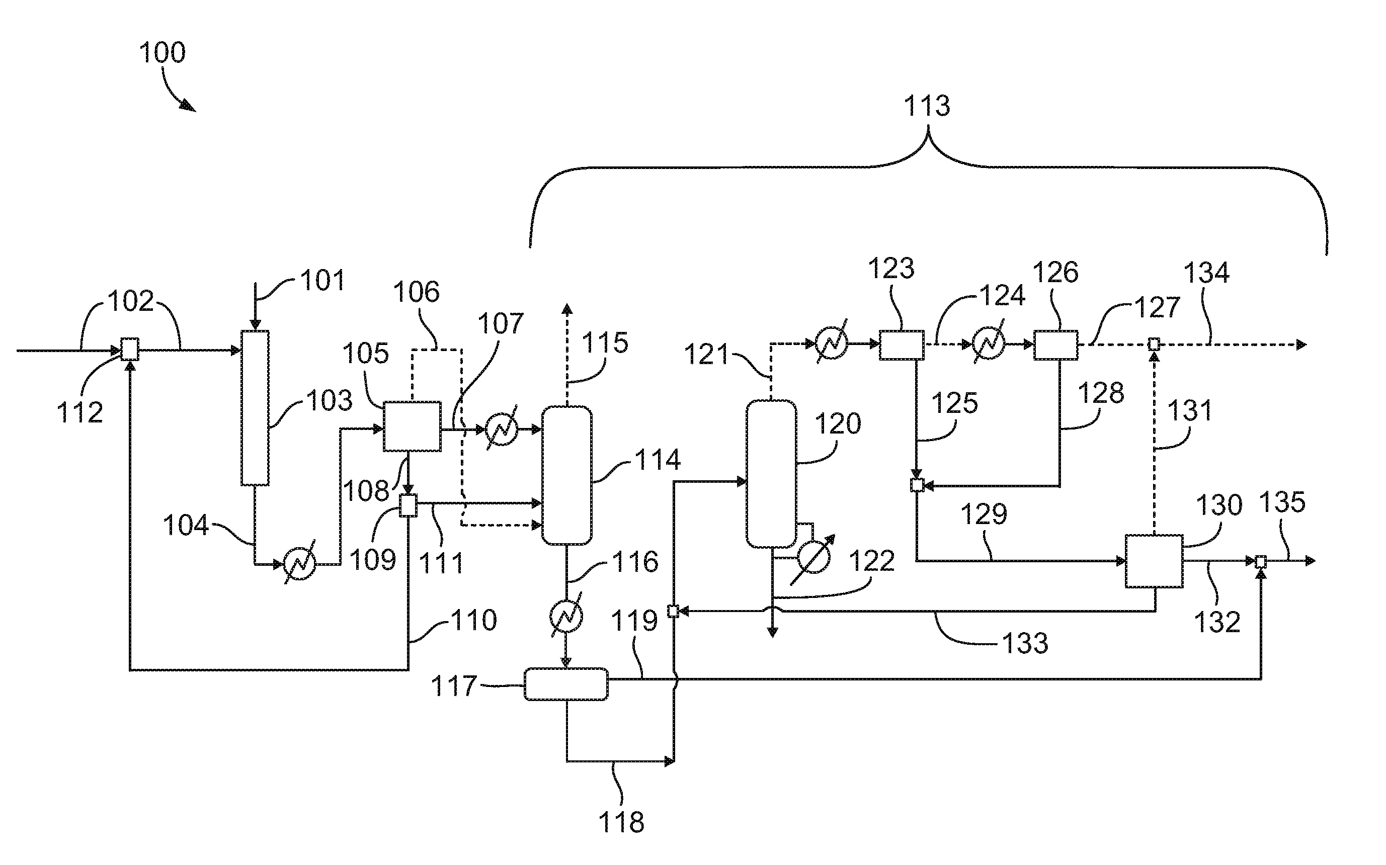
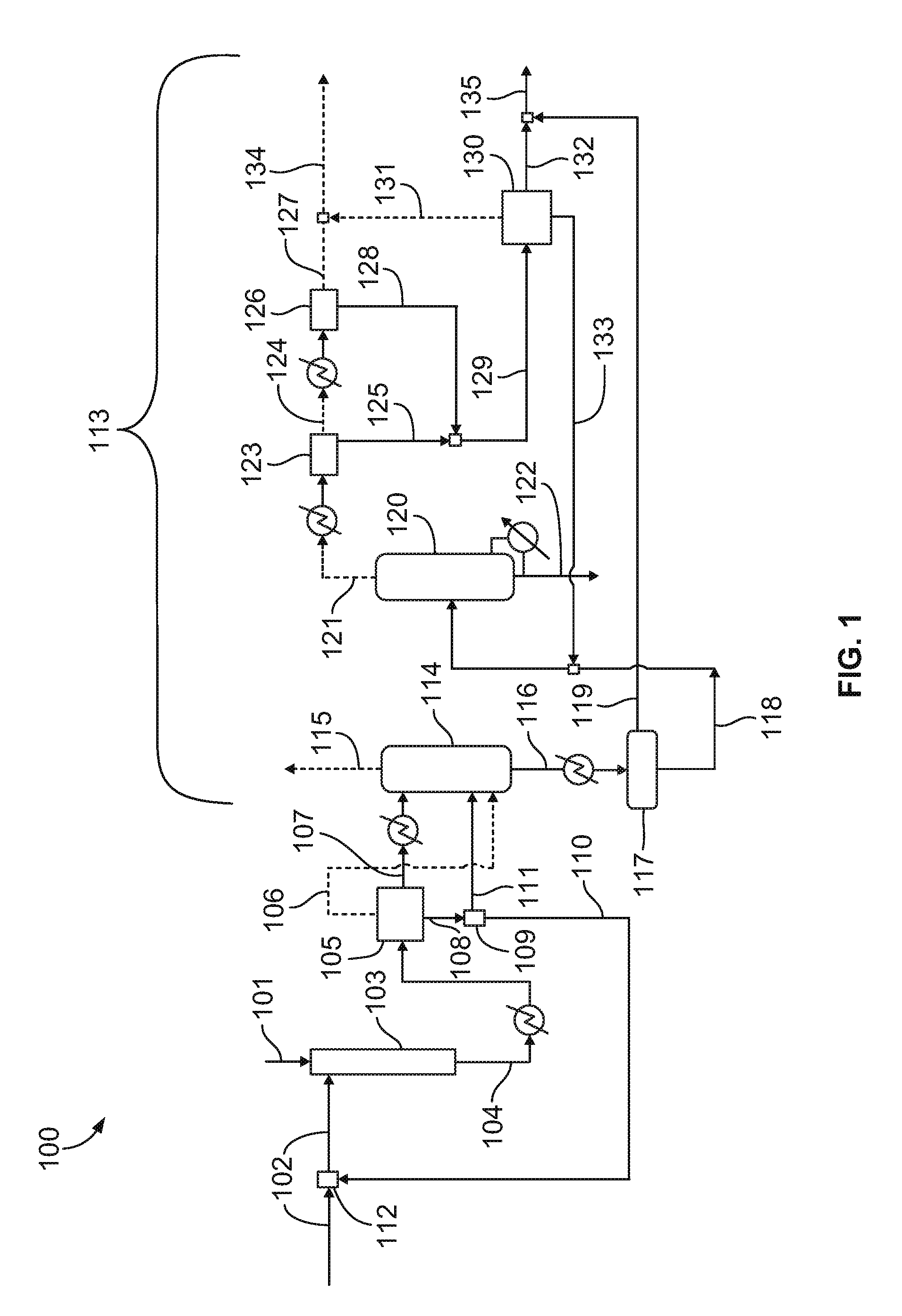
[0035]The product stream is then quenched in an after-cooler to about 38 degrees Celsius and subsequently flashed into a gas phase, an aqueous phase, and an oil phase. The aqueous phase comprises almost all of the water...
example 2
Nitration Scheme with Aqueous Recycle
[0038]In an illustrative embodiment, at approximately the same process conditions as in Example 1, 75-85 percent of the aqueous stream coming out of the post-reactor flash is recycled to the nitration reactor as nitric acid diluent. The oil phase is cooled to 16 degrees Celsius before feeding to the absorber to reduce loss of nitropropanes in the overhead. The gas stream is steam stripped of all volatiles at a pressure of 44.1-73.5 psi (3-5 atm) and the resulting stream, which is essentially un-reacted propane and gas byproducts, is then compressed to a pressure of 147 psi (10 atm) in a two-stage compressor before routing it to the propane recovery section. The bottom stream from the absorber is cooled and phase-separated into an aqueous and an oil phase. The aqueous phase is further sent to the nitropropane recovery column which is operated at a pressure of 14.7 psi (1 atm) to recover the dissolved nitropropanes. Water, organic acids, and nitric...
example 3
Propane Nitration with No Nitroparaffins in the Reactor Feed
[0040]Propane is reacted with 20 weight percent aqueous nitric acid with the above described reactor at a reactor pressure of 1400 psi (96.7 atm), a reaction temperature of 285° C., a residence time of 153 seconds, and a propane to nitric acid mole ratio of 1.81:1. The feed composition and the reaction product stream composition are summarized in Table 5.
TABLE 5Feed composition and reaction product stream compositionComponentFeed (g)Reaction Product (g)Propane1185769Nitric Acid93820.5Water37284287Acetic Acid0110Acetone011.1Nitromethane06.1Nitroethane04.32-nitropropane04911-nitropropane0752,2-dinitropropane08.0Nitric oxide048.5Nitrous oxide05.6Nitrogen012.7Carbon monoxide024.0Carbon dioxide0221.7
[0041]Key performance metrics for this reaction are summarized in Table 6.
TABLE 6Key performance metrics for nitration of propanewith no nitroparaffins in the reactor feedNitric acid conversion (%)97.8Propane conversion (%)35.1Nitric...
PUM
| Property | Measurement | Unit |
|---|---|---|
| weight percent | aaaaa | aaaaa |
| weight percent | aaaaa | aaaaa |
| weight percent | aaaaa | aaaaa |
Abstract
Description
Claims
Application Information