Audio signal amplifier circuit

a technology of amplifier circuit and amplifier circuit, which is applied in the direction of amplifier with semiconductor devices/discharge tubes, transducer casings/cabinets/supports, etc., can solve the problem of audible noise output of headphones, and achieve the effect of widening the input voltage range and reducing the current consumption of the circui

a technology of amplifier circuit and amplifier circuit, which is applied in the direction of amplifier with semiconductor devices/discharge tubes, transducer casings/cabinets/supports, etc., can solve the problem of audible noise output of headphones, and achieve the effect of widening the input voltage range and reducing the current consumption of the circui

US20110158435A1Active Publication Date: 2011-06-30ROHM CO LTD

Image

  • Audio signal amplifier circuit
  • Audio signal amplifier circuit
  • Audio signal amplifier circuit

Examples


first embodiment

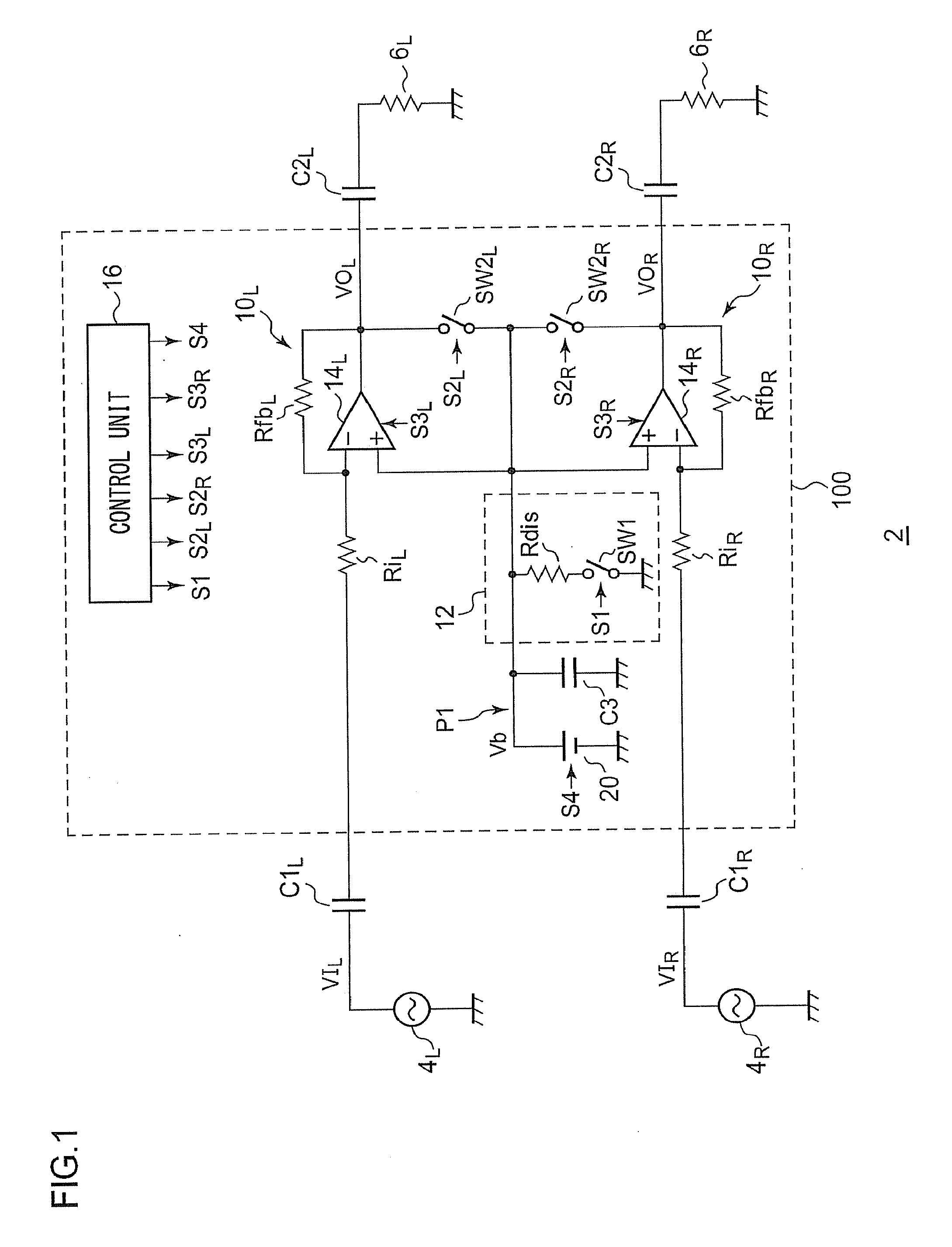
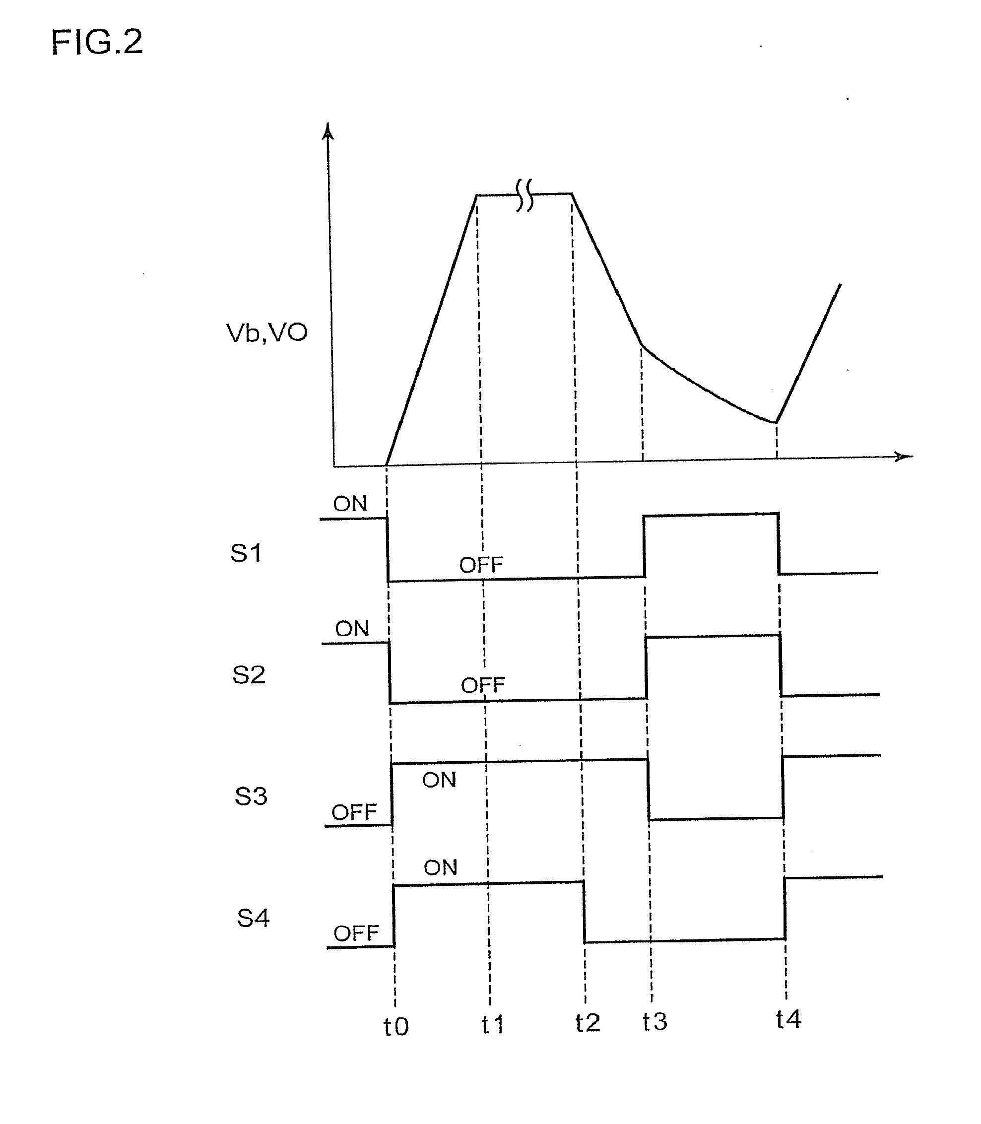
[0056]FIG. 1 is a block diagram which shows a configuration of an audio playback apparatus 2 including an audio signal amplifier circuit (headphone amplifier) 100 according to a first embodiment. The audio playback apparatus 2 has a function of outputting an audio signal (voice signal), and is mounted on various electronic devices such as cellular phone terminals, portable audio players, headphone amplifiers, non-portable audio components, etc.

[0057]The audio playback apparatus 2 includes sound sources 4, input capacitors C1, output capacitors C2, an audio signal amplifier circuit 100, and headphones 6. The audio playback apparatus 2 shown in FIG. 1 has a two-channel stereo configuration. It should be noted that the present invention is not restricted to such an arrangement. Also, the audio playback apparatus 2 may have a monaural configuration or a multi-channel configuration having three or more channels. Note that, in order to distinguish between the two stereo channels, these tw...

second embodiment

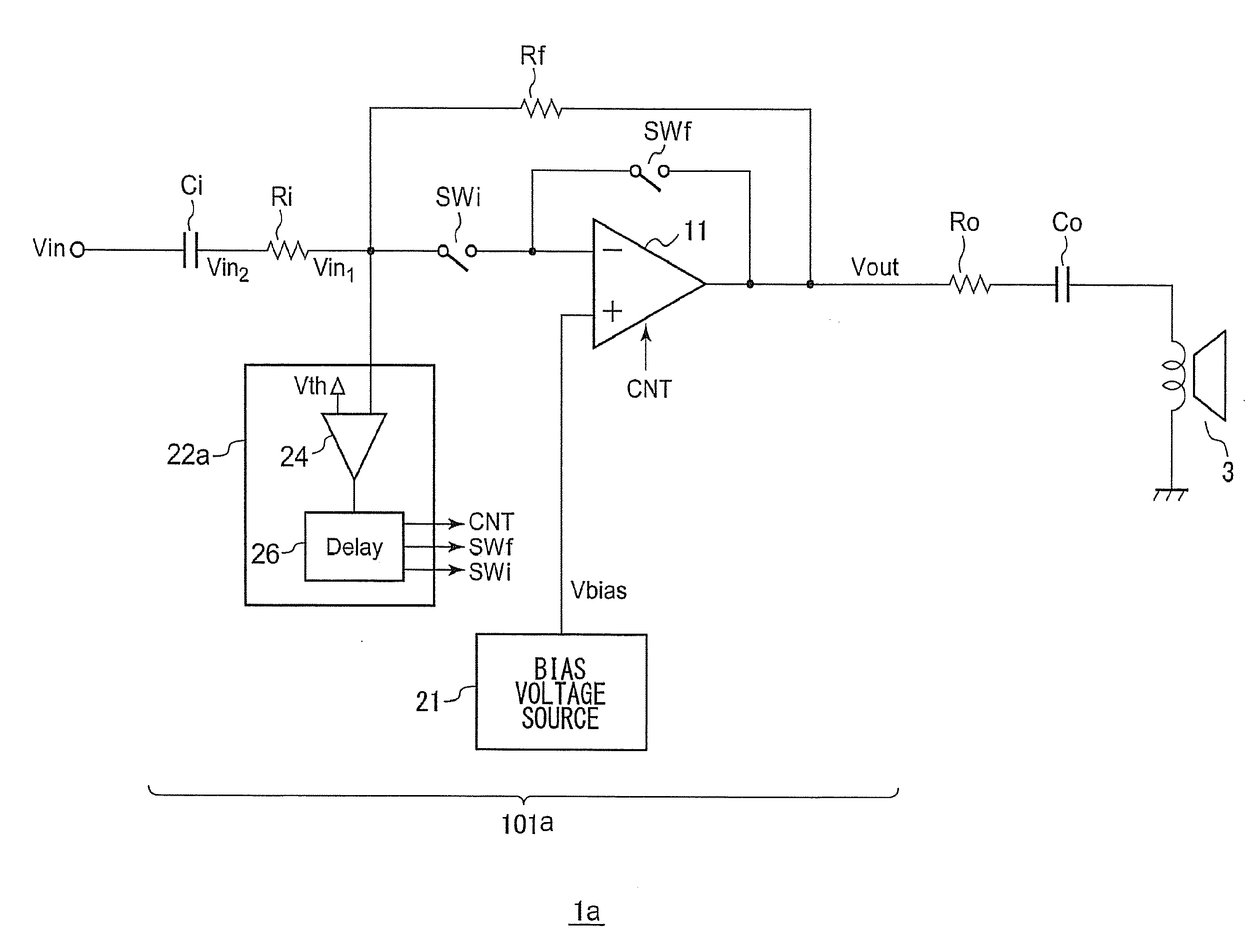
[0094]FIGS. 7A and 7B are circuit diagrams which show a configuration of an inverting amplifier 101 according to a second embodiment. FIG. 7A shows the overall configuration of the inverting amplifier 101.

[0095]The inverting amplifier 101 is mounted on an electronic device 1 having an audio playback function. The inverting amplifier 101 amplifies an audio signal (input signal Vin), and drives an electroacoustic transducer such as speakers, headphones, or the like, provided as a downstream component. The electroacoustic transducer 3 and the inverting amplifier 101 are coupled via an output resistor Ro and an output capacitor Co.

[0096]The inverting amplifier 101 includes an operational amplifier 11, a bias voltage source 21, a control unit 22, an input resistor Ri, a feedback resistor Rf, and an input capacitor Ci.

[0097]A bias voltage Vbias, which is generated by the bias voltage source 21, is input to the non-inverting input terminal (+) of the operational amplifier 11. In a case in ...


PUM


Abstract

An inverting amplifier which drives headphones via an output capacitor includes: an operational amplifier, an input resistor having a first terminal via which an audio signal to be amplified is received, and a second terminal connected to an inverting input terminal of the operational amplifier; and a feedback resistor having a first terminal connected to an inverting input terminal of the operational amplifier, and a second terminal connected to the output terminal. A reference voltage source generates a bias voltage Vb, and supplies it to the non-inverting input terminal. A discharging path includes a discharging resistor and a first switch arranged in series between an output terminal of the reference voltage source and an fixed voltage terminal. A second switch is arranged between the output terminal of the operational amplifier and a node on the discharging path where the electric potential is higher than it is at the discharging resistor.

Description

BACKGROUND OF THE INVENTION[0001]1. Field of the Invention[0002]The present invention relates to an audio signal amplifier circuit.[0003]2. Description of the Related Art[0004]Audio devices or electronic devices having an audio playback function include an audio signal amplifier circuit configured to amplify a weak electrical signal, and to output the electrical signal thus amplified to an electroacoustic transducer such as speakers, headphones, earphones, or the like (which will be collectively referred to as “speakers” hereafter).[0005]In some cases, a coupling capacitor is arranged between the audio signal amplifier circuit and the speaker in order to prevent a DC current from flowing from the audio signal amplifier circuit to the speakers. With an arrangement which allows the user to detachably connect headphones or earphones to the device, if the user removes and inserts the headphones during audio playback, unexpected charging or discharging occurs at the coupling capacitor, a...

Claims


Application Information

Patent Timeline
30 Jun 2011
Publication
US20110158435A1
IPC
H03F99/00; H03F3/45
CPC
H03F1/0261; H03F3/45183; H03F3/45475; H03F2200/03; H03F2203/45528; H03F2203/45536; H03F2203/45622; H03F2203/45548
Inventors
ONO, KATSUYUKI; KAWAMURA, AKINOBU