Feature Tracking Using Ultrasound

Inactive Publication Date: 2011-07-14
ELEKTA AB
View PDF101 Cites 36 Cited by
  • Summary
  • Abstract
  • Description
  • Claims
  • Application Information

AI Technical Summary

Benefits of technology

[0018]In some versions, the processor determines if the displacement exceeds a displacement threshold (an upper limit of spatial displacement of the feature of interest, for example) and if so, provide instructions to obtain an updated three dimensional image of the region of interest sooner than would be obtained based on the first periodicity. The processor may also determine if the displacement exceeds a safety threshold. If so, the processor can provide instructions to halt the medical procedure, thereby allowing for adjustments to be made to the patient's orientation with respect to a treatment device and/or to the orientation of the treatment device itself prior to reinstating the procedure.
[0019]In some cases, the sy

Problems solved by technology

However, continuous monitoring is not achievable with this methodology because the x-ray imaging exposure is unbearably high, with an image frequency of 30 seconds being the currently acceptable limit.
Such procedures still require undesirable extra radiation as well as an invasive fiducial implantation procedure.
Further, various surface monitoring technologies have been developed for cyclical intrafractional motion, but these do not provide internal information and are not sufficient in many applications, particularly when random motion occurs.
Some of these di

Method used


Image

  • Feature Tracking Using Ultrasound
  • Feature Tracking Using Ultrasound
  • Feature Tracking Using Ultrasound

Examples


Embodiment Construction

[0030]Throughout the following descriptions and examples, aspects and embodiments of the invention are described in the context of tracking intrafractional motion during the delivery of radiotherapy. However, it is to be understood that the present invention may be applied to tracking attributes of virtually any feature within or on a patient during any form of medical procedure requiring anatomical tracking, such as external beam and brachytherapy, cryotherapy, hyperthermia, high intensity focused ultrasound treatments (HIFU)) and / or various forms of imaging (e.g., CT, 4DCT, PET, US, SPECT, and MRI).

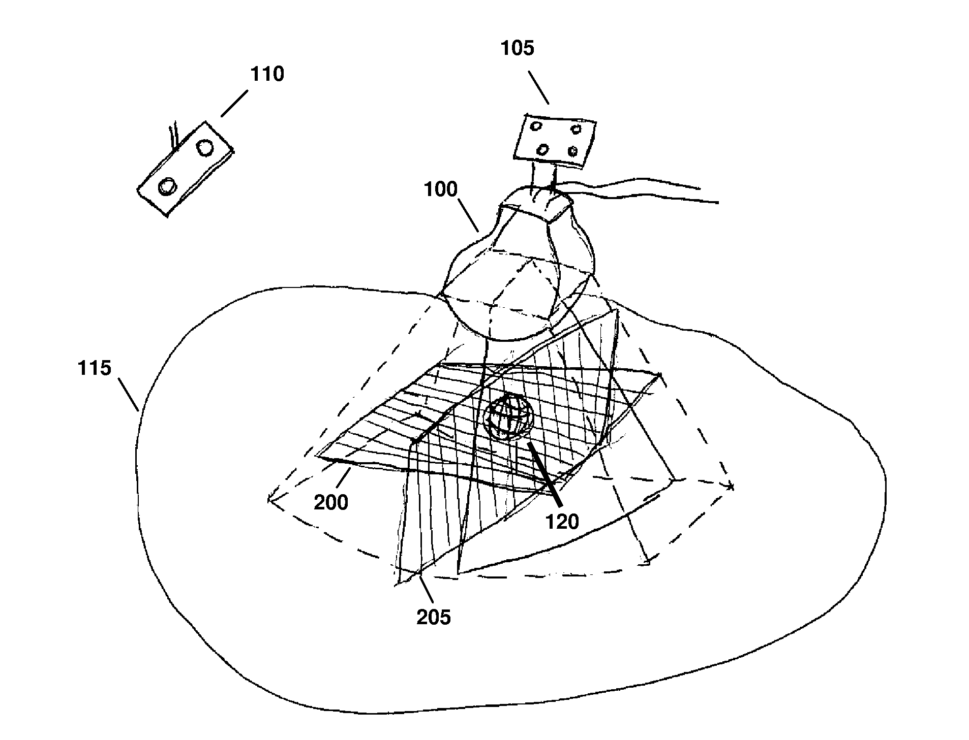
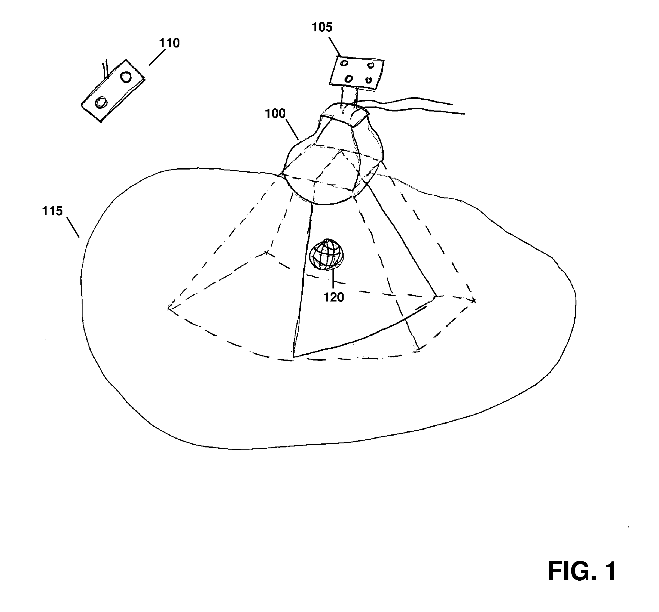
[0031]Referring to FIG. 1, a motorized, mechanically sweeping three-dimensional ultrasound probe 100, which is of particular use in this application, contains a two-dimensional probe inside of a housing, the two-dimensional probe being able to sweep at different angles within the housing, controlled by a motor. In certain applications, tracking markers 105 are affixed to the probe handl...


PUM


Abstract

Various implementations of the invention provide techniques and supporting systems that facilitate real-time or near-real-time ultrasound tracking for the purpose of calculating changes in anatomical features during a medical procedure. More specifically, anatomical features within a patient undergoing a medical procedure are tracked by obtaining temporally-distinct three dimensional ultrasound images that include the feature of interest and obtaining a targeted subset of ultrasound images focused on the feature. Based on the targeted subset of ultrasound images, a displacement of the feature is determined and image parameters used to obtain the targeted subset of ultrasound images are adjusted based on the displacement. This results in a time-based sequence of three dimensional images and targeted ultrasound images of the feature that identify changes in the position, size, location, and/or shape of the feature.

Description

CROSS-REFERENCE TO RELATED APPLICATIONS[0001]This application claims priority to and the benefit of U.S. provisional patent application Ser. No. 61 / 294,294, filed Jan. 12, 2010, and U.S. provisional patent application Ser. No. 61 / 323,064, filed Apr. 12, 2010, each entitled “Feature Tracking Using Ultrasound.”TECHNICAL FIELD[0002]This invention relates to methods for tracking features during a medical procedure.BACKGROUND INFORMATION[0003]One purpose of radiotherapy is to target a specified anatomical region suspected of having either gross or suspected microscopic disease (sometimes referred to as the clinical treatment volume, or “CTV”) with radiation while sparing surrounding healthy tissues and at-risk organs. Typically, a physician outlines the CTV on one or more planning images, such as a computed tomography (CT) image, magnetic resonance (MRI) image, three-dimensional ultrasound (3DUS) image, or a positron emission tomography (PET) scan. A treatment plan is then developed whic...

Claims


Application Information

Patent Timeline
IPC IPC(8): A61B8/08A61N5/00
CPCA61B8/085A61B8/587A61B8/4461A61B8/4472A61B8/483A61B8/58A61B19/5244A61B2019/5255A61B2019/5263A61B2019/5265A61B2019/5276A61N5/1049A61N2005/1058G06T7/2046G06T2207/10132G06T2207/10136G06T2207/30004A61B8/4263A61B8/4245A61B2034/2055A61B2034/2063A61B34/20A61B2034/2065A61B2090/378G06T7/251G06T7/0012A61B8/54A61N5/1067A61N2005/1074
Inventor LACHAINE, MARTINTREMBLAY, SEBASTIENLATHUILIERE, FABIENNEFALCO, TONY
Owner ELEKTA AB
Why Eureka
Try Eureka