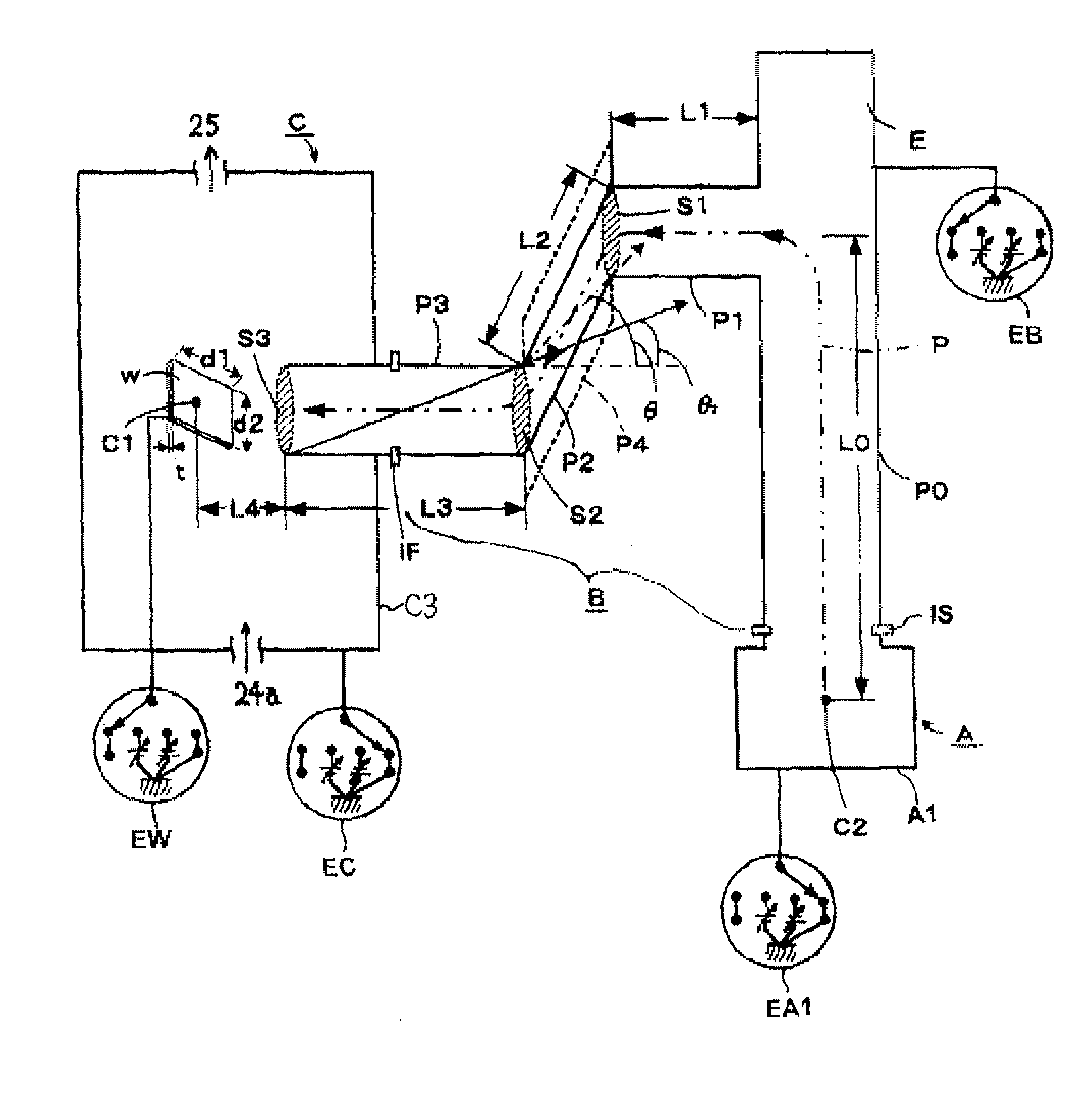
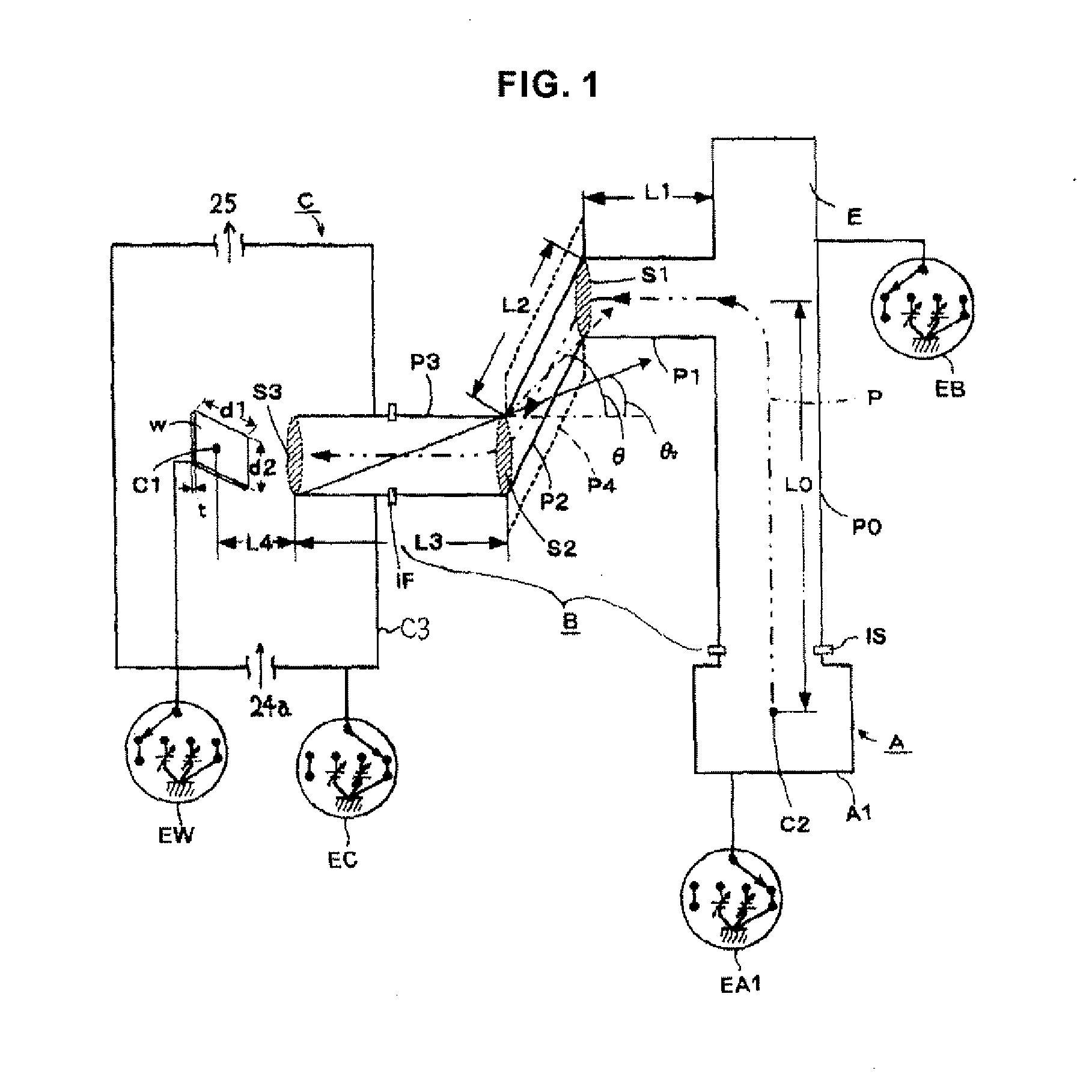
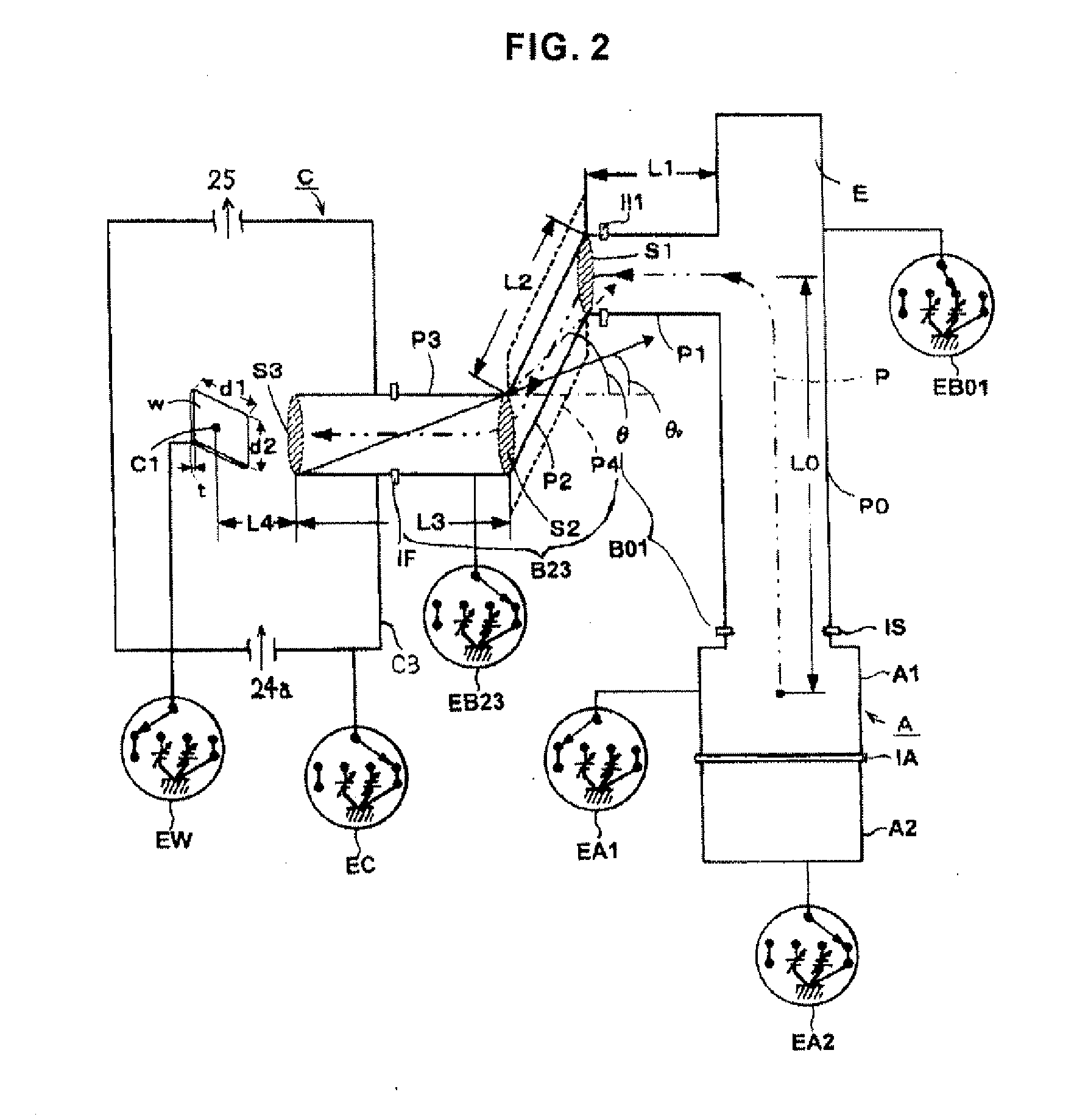
[0042]According to the first form of the present invention, by interposing a starting end side insulator between said plasma generating portion and said plasma transport tube, and interposing a finishing end side insulator between said plasma transport tube and said plasma processing portion, a complete electrical independence is achieved by said plasma generating portion, said plasma transport tube, and said plasma processing portion. As a result, an electric influence from said plasma generating portion and said plasma processing portion toward the plasma transport tube is completely blocked, the plasma transport tube that is usually formed from a
metal becomes constant in terms of the electric potential as a whole, and an electric
potential difference does not exist in the plasma transport tube. Because there is no electric
potential difference, an
electrical force, based on electric
potential difference, toward charged particles is not generated. Because electrically charged droplets are one type of charged particles, an
electrical force does not act on electrically charged droplets in a plasma transport tube in a constant electric potential state, and therefore electrically charged droplets can be handled in the same manner as neutral droplets. Therefore, by means of the geometric removal method of neutral droplets described below, it becomes possible for electrically charged droplets to be removed together with neutral droplets while advancing through the plasma transport tube. Because of this, the plasma supplied from the plasma transport tube becomes a high purity plasma from which neutral droplets and electrically charged droplets have been removed by the neutral droplet removal structure, and by this high purity plasma, a high purity
plasma treatment is made possible toward an object to be treated in the plasma processing portion.
[0043]According to the second form of the present invention, because said plasma transport tube is divided into small transport tubes of multiple steps by means of an intermediate insulator, the small transport tubes become electrically independent from one another, and an electrical influence toward one small transport tube from the other remaining small transport tubes can be blocked. Of course, the whole of the small transport tubes is insulated by the starting end side insulator and the finishing end side insulator from the plasma generating portion and the plasma processing portion, and the electrical insulation state of the small transport tubes is improved even more than the first form. As a result, the individual small transport tubes are maintained to a constant electric potential, an
electrical force toward electrically charged droplets is not exerted at all in each small transport tube, and it becomes possible for electrically charged droplets to be removed only by a geometric removal structure, in the same manner as neutral droplets.
[0044]According to the third form of the present invention, a bias power supply is not connected at all to said plasma transport tube or said multiple small transport tubes, and it becomes an electric floating state in which an electric potential is not provided forcibly. The plasma transport tube and the divided small transport tubes are
metal tubes, and if a bias power supply is not connected, the whole of the metal tube is made to a constant electric potential. An
electric charge is not injected from the outside because of the insulator, and an
electric charge does not exist in the plasma transport tube and the small transport tubes. Because of this, the metal tubes such as the plasma transport tube or the small transport tubes are maintained to a constant electric potential. There is no case in which an
electric charge is injected from air, but here, a hypothetical case in which a
charge injection from air into the
Metal tubes is assumed. Then, electric charges are injected into the metal tube, but the electric charges only become distributed throughout the metal tube surface by the repulsive force between the electric charges, and therefore do not remain within the metal tube. As a result, even without bringing up Gauss's theory of
electromagnetism, it is obvious that the electric potential of the metal tube surface becomes constant. Therefore, in the first form, the whole of said plasma transport tube becomes constant in term of the electric potential, and in the second form, the whole of said multiple small transport tubes becomes constant in term of the electric potential. Because of this, an
electric force is not exerted on electrically charged droplets advancing through these metal tubes, and it becomes possible to remove electrically charged droplets by a geometric structure of the plasma transport tube or the small transport tubes, in the same manner as neutral droplets.
[0045]According to the fourth form of the present invention, because a bias power supply for transport path is connected to said plasma transport tube or each of said small transport tubes, said plasma transport tube or said small transport tubes will have a predetermined electric potential that is provided forcibly by the bias power supply. Said bias power supply can provide a variable positive electric potential, a variable negative electric potential, or GND (ground electric potential). As for the variable range of the positive electric potential, 0-50 (V) is desirable, and as for the variable range of the negative electric potential, 0 to −50 (V) is desirable. The choice of any one of a positive electric potential, a negative electric potential, or GND is chosen by the density of the supplied plasma to the plasma processing portion, and the removal efficiency of the electrically charged droplets. Also, the adjustment of the magnitude of the positive electric potential and the magnitude of the negative electric potential is done too by said
plasma density and said removal efficiency of the electrically charged droplets. The present inventor found that in a case where said plasma transport tube is not divided, setting said plasma transport tube in an electrically floating state (bias electric potential not provided) is experimentally favorable. The present inventor found that when said plasma transport tube is divided in two, setting the small transport tube which is near the plasma generating portion to −5 to −10 (V), and the small transport tube which is near the plasma processing portion to GND gives a good result, and therefore is favorable with the
experimental system currently in operation. Because these favorable configurations depend upon the experimental device and the experimental environment, there can also be other bias electric potential designs.
[0046]In addition, when a positive electric potential is provided to the transport tube by a bias power supply, the plasma of positive
electricity is repelled and the plasma transport efficiency increases, and the film
formation rate in the plasma processing portion increases. However, the removal efficiency of electrically charged droplets tends to decrease, and the amount of droplets in the formed film tends to increase. On contrary, when a negative electric potential is provided to the transport tube by a bias power supply, the plasma of positive
electricity is drawn and the plasma transport efficiency falls, and the
deposition rate in the plasma processing portion decreases. However, the removal efficiency of electrically charged droplets tends to increase, and the amount of droplets in the formed film tends to decrease. Therefore, there is an inverse relation between the film
formation rate and the number of droplets deposited in a formed film. Also, cases exist where, even when droplets are decreased, the amount of droplets increase eventually when the
deposition rate decreases, and the film formation time for obtaining a predetermined film thickness increases. Therefore, to satisfy both the
deposition rate and the droplet
number density, it is necessary to delicately adjust the electric potential provided by the bias power supply. Because of this, by dividing the plasma transport tube into multiple small transport tubes, and adjusting the bias electric potential of each small transport tube mutually, it becomes possible to satisfy both the film
formation rate and the droplet
number density. The more the number of partitions increases, the easier said adjustment becomes.
[0047]According to the fifth form of the present invention, an arbitrary bias electric potential can be provided by electrically insulating the plasma generating portion container and the target exchange portion container by the inter-container insulator, setting said plasma generating portion container in an electric floating state, and attaching the bias power supply for container to said target exchange portion container. When said plasma generating portion container is set to an electric floating state, said plasma generating portion container does not exert an electrical influence to the generated plasma, and the advancement of the plasma to the plasma transport tube can be carried out smoothly. Also, a variable positive electric potential, a variable negative electric potential, or GND can be provided to said target exchange portion container, and an optimum setting of the plasma processing apparatus becomes possible. In the currently operating experiment
system, the choice of GND is favorable from the point of view of safety, but because it depends on the experimental device and the experimental environment, other bias electric potential designs are also possible.


