
Device for traversing vessel occlusions and method of use

a technology of occlusion and device, applied in the field of energy efficient devices, can solve the problems of long procedures with potentially adverse effects on patients, limited success of devices for opening these occlusions, and inability to meet patient needs, so as to improve efficiency, reduce the effect of sensitiveness and more efficient energy transfer

Inactive Publication Date: 2011-08-11
MEDINOL LTD
View PDF4 Cites 20 Cited by
  • Summary
  • Abstract
  • Description
  • Claims
  • Application Information

AI Technical Summary

Benefits of technology

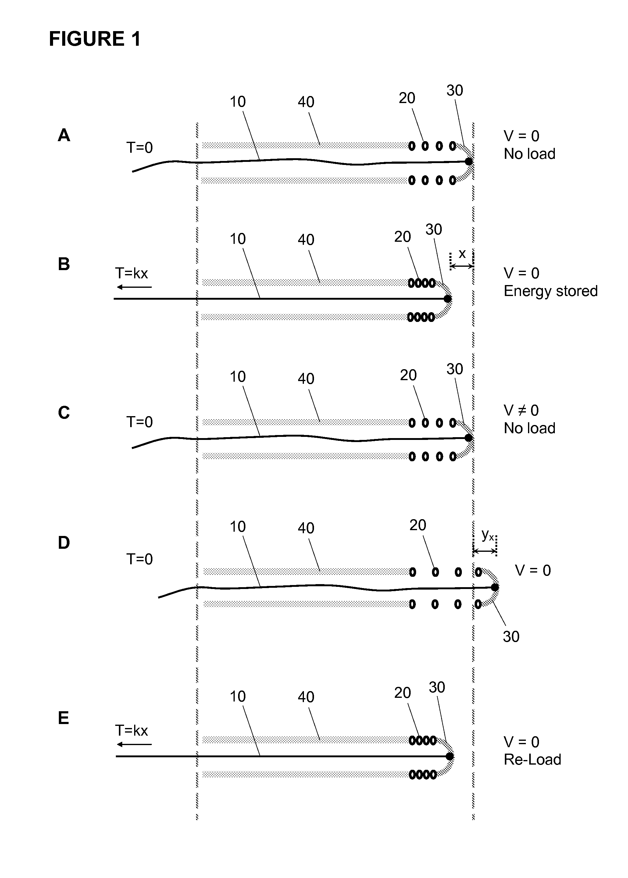
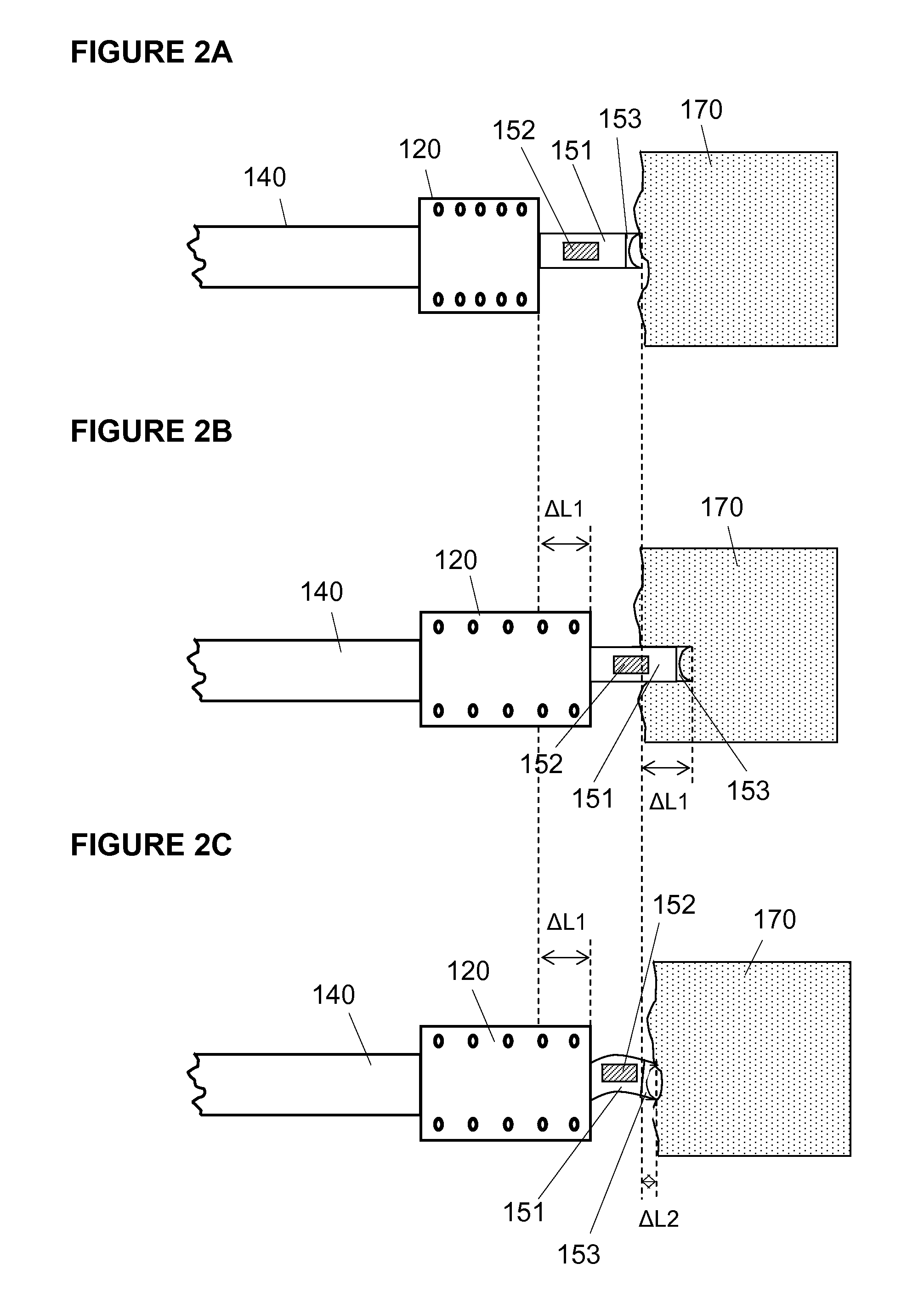
[0012]It is an object of the invention to provide an improved apparatus for penetrating a vessel occlusion and / or traversing a partial occlusion, where the apparatus has a vibratable member that is made to vibrate in an improved manner, namely, by more efficient energy transfer from the external energy source to the distal part of the catheter. The increased efficiency derives from the pulling wire-spring combination of the apparatus. In particular, the apparatus generates a vibration force that oscillates the vibratable member by a pulling force rather than pushing or combined pulling-pushing force. The apparatus of the invention is less sensitive to unpredictable geometry such as the sometimes tortuous curvature of blood vessels than PCI devices that use pushing forces.
[0017]The system of the invention comprises the apparatus of the invention and a control unit adapted for controlling the vibrational energy source, and thereby adjust the frequency and / or amplitude of vibration of the vibratable member. Preferably, the control unit may adjust the vibrational energy source to generate a vibration force suitable for the occlusion morphology and hardness, the vibration force having at least one frequency and at least one amplitude. Suitable vibration force may be achieved by adjusting the frequency, e.g., from several Hz to several hundred Hz, and / or adjusting the pulling amplitude, so that the penetration force of the vibration is minimized and is appropriate for the occlusion morphology and hardness. The at least one frequency and at least one amplitude generated by the vibrational energy source may be adjusted via the control unit to suit the occlusion being treated. Optionally, the system of the invention further comprises an operator interface unit and a sensor to assist the operator in controlling the frequency and amplitude of vibration of the vibratable member based on feedback from the sensor regarding hardness of the occlusion and / or Δy of the spring member.
[0018]It is believed that by providing the minimal force necessary to penetrate an occlusion, safety of the recanalization procedure is increased and potential damage to the body lumen, e.g., an artery, is reduced compared to recanalization devices in the art. Accordingly, the frequency and / or amplitude of vibration of the vibratable member may be changed manually by the physician operator to adjust for the hardness of the particular occlusion being treated, based on the operator's skill and experience. Alternatively, the frequency and amplitude of vibration may be adjusted automatically or manually based on measurements of the hardness of the occlusion. Where the hardness of the occlusion is to be measured, the apparatus of the invention may further comprise a sensor or strain gauge. In such embodiments, the control unit may further comprise a processor, or an operator interface unit comprising a processor may be used, the processor being capable of analyzing input from the sensor or strain gauge to calculate tissue hardness or amplitude of vibration and the operator interface unit being capable of providing the calculations in a user-readable form. Either the control unit or operator interface unit may comprise one or more adjustor means for the operator to adjust manually the frequency and / or amplitude of the pulling force generated by the vibrational energy source. Optionally, the operator interface unit may further comprise a display unit for displaying information regarding occlusion hardness.
[0020]The invention further encompasses a method of oscillating the vibratable member, a method of using the apparatus or system for recanalization of an occluded body lumen, such as a blood vessel, and a method of controlling the force of vibration in the apparatus. The result is a versatile and efficient energy delivery apparatus, system and method for penetrating a total occlusion and / or improving deliverability of the catheter through partially occluded body lumens.

Problems solved by technology

An occlusion can result in hypertension, ischemia, angina, myocardial infarction, stroke and even death.
As occlusion morphology is complicated and varies from patient to patient, common methods and devices for opening these occlusions have had limited success and require long procedures with potentially adverse effects on the patient.
Such adverse effects include perforation of blood vessel wall, high radiation dose or damage to kidneys due to extensive use of angiographic contrast material.
The harder materials are more difficult to penetrate, requiring a significant amount of energy, the softer materials require less energy.
Therefore, opening an occlusion requires transfer of relatively extensive energy to the distal end of a catheter or guide wire, especially when calcification is present.
The latter means for opening occlusions suffer from significant energy loss between the energy source at the proximal end of the catheter and the driller located at the distal end of the catheter, as well as limited working life due to material fatigue.
The long length and narrow diameter combine to make wire breakage a common problem due to the stress and wear from the high energy pulses.
Guide wires stiff enough to penetrate hard occlusions have the disadvantage that their inflexibility and straight tips make navigating through tortuous vessels difficult and increase the risk of vessel perforation.
Rigid materials that are sufficiently flexible to accommodate the highly tortuous vessels have the problem of buckling, due to the proximal location of the pushing source.
Buckling results in energy loss by transfer to transverse forces and friction against the lumen housing the rigid material.
All such devices provide limited success rate ranging from 40-70%.
As previously described, current devices suffer either from an insufficient amount of energy transferred to the distal end of the device or a mismatch between the type of energy delivered and the type of occlusion, sometimes resulting in too much force being applied and thereby increasing the risk of damage, or even perforation, of the lumen wall.
However, such energy transfer mechanisms suffer from significant, yet unpredictable (i.e., variable), energy loss due to energy transfer to the housing tube (e.g., catheter lumen).
This is a particular problem when the rigid wire bends to conform to the anatomy of the blood vessel.
(2) Buckling of the wire, a situation that causes the axial force to be shifted to transverse forces and results in increased friction forces within the housing lumen.
Further, if the axial force is increased to compensate for the energy losses, the buckling is exacerbated, making axial oscillation, and in particular controllable axial oscillation, even more difficult to achieve.
Friction created by the bent wire against the lumenal surface of the catheter causes the rigid wire to be pinned at some point.
If the friction at the pinned point is larger than the buckling threshold, a buckling will occur and adversely affect the pushability of the wire.
If the length of the straight portion of the rigid wire preceding the point of resistance is long enough, however, the rigid wire will buckle before the pushing force becomes large enough to overcome the friction.
This explains why it is difficult to transmit a force to one end of a winding rigid wire by pushing from the opposite end, because the rigid wire is expected to buckle.

Method used


Image

  • Device for traversing vessel occlusions and method of use
  • Device for traversing vessel occlusions and method of use
  • Device for traversing vessel occlusions and method of use

Examples


Embodiment Construction

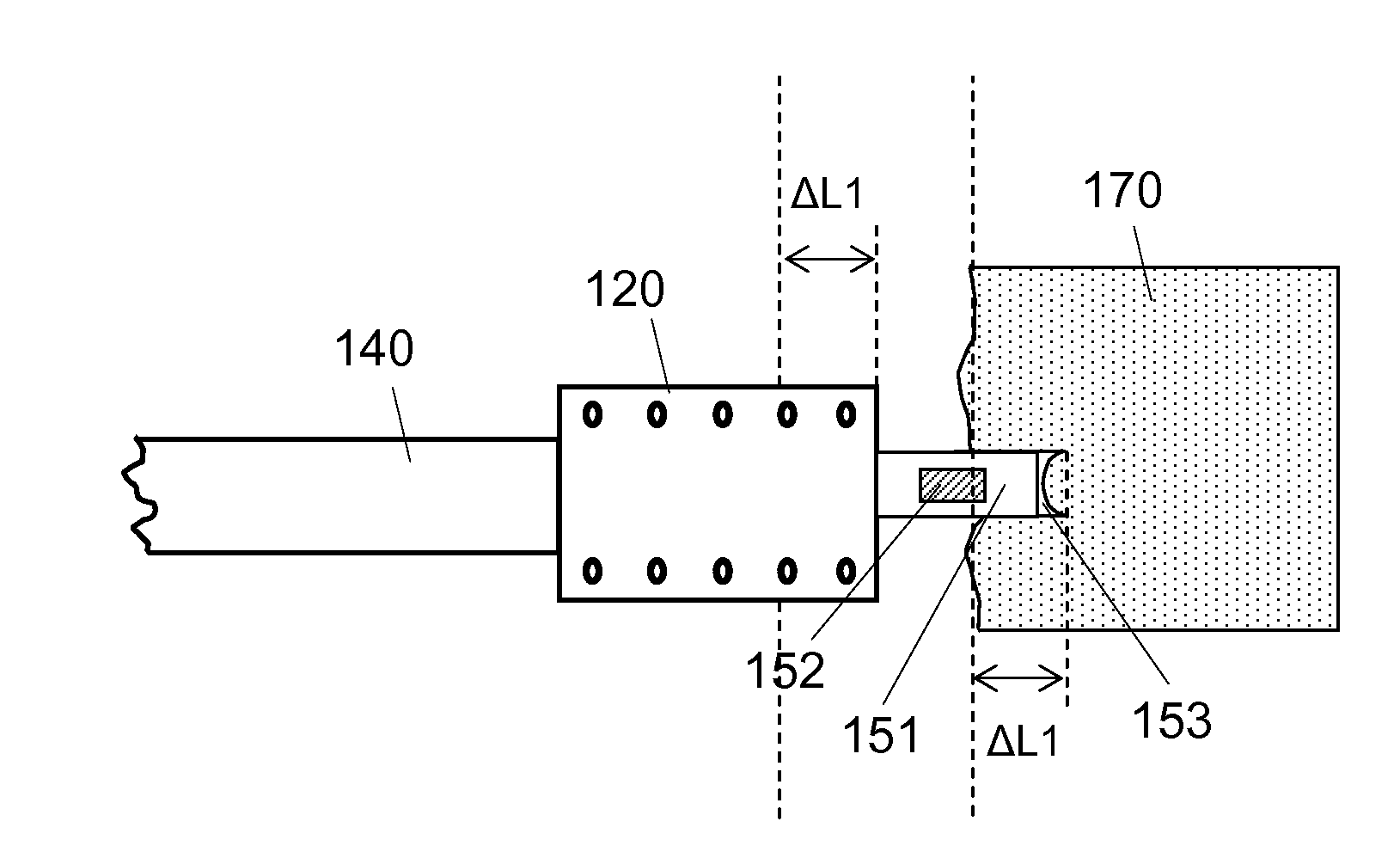
[0025]In order to overcome the mechanical energy loss limitations of prior art devices, the apparatus of the invention uses a distal spring-like element that can store potential energy. The potential energy is loaded and released to kinetic energy at desired frequency by pulling and releasing a flexible pulling member. As used herein, the term “flexible” is intended to mean capable of flexing laterally without any inertia moment, e.g., to accommodate tortuous vessels, but not longitudinally—e.g., the pulling member should be minimally stretchable or extensible lengthwise. By “releasing the pulling member” is meant that the tension—generated in the pulling member by pulling the pulling member—is released. In parallel to the release of tension in the pulling wire, the potential energy of the spring element is released to kinetic energy. The stored energy of the spring element is released to the surrounding tissue or occlusion via a vibratable member which impacts the occlusion. An adv...


PUM


Abstract

An apparatus, system and method for re-canalization or opening a passage through an occlusion in a blood vessel is provided. The apparatus and method, which are appropriate for both cardiovascular as well as peripheral vessels, use a pulling member and a spring element, for example a compression spring, to oscillate a vibratable member, and the system of the invention includes the apparatus and a control unit to permit the frequency or amplitude of oscillation of the vibratable member to be adjusted. Also provided is a method for oscillating a vibratable member using a pulling member and a spring element. The apparatus and system are useful not only for penetrating a total or partial occlusion, but also to improve deliverability of a catheter through a partially occluded vessel or a tortuous vessel.

Description

FIELD OF THE INVENTION[0001]The invention is directed to an energy efficient apparatus and method of using that apparatus for penetrating a total occlusion of a blood vessel during percutaneous coronary intervention (“PCI”) or improving deliverability of a percutaneous transluminal angioplasty (PTA) catheter through a partial occlusion of a blood vessel. In particular, the apparatus provides energy transfer to the distal tip of the PCI device via a pulling force, to penetrate the occlusion with minimal energy loss. The apparatus is also applicable to percutaneous intervention procedures in peripheral arteries.BACKGROUND OF THE INVENTION[0002]Medical science has long sought effective treatments for disease conditions involving stenosis (narrowing or obstruction) of the lumen of an artery. This condition, known generally as an occlusion, occurs in patients suffering from atherosclerosis, which is characterized by an accumulation of fibrous, fatty or calcified tissue in the arteries, o...

Claims


Application Information

Patent Timeline
Patent Type & Authority Applications(United States)
IPC IPC(8): A61B17/22
CPCA61B17/22012A61B2017/22014A61B2017/22015A61M25/0116A61B2017/925A61B2017/928A61B2017/22094A61M25/04A61B2017/22001A61B2017/22027
Inventor PANSKY, AMIR
Owner MEDINOL LTD
Learn More