Solid electrolyte capacitor

a solid electrolyte capacitor and electrolyte technology, applied in the manufacture of electrolytic capacitors, capacitor details, etc., can solve the problems of requiring capacitors, laptop computers and mobile electronic devices are strongly expected to consume less power to operate with their batteries, and drop voltage, so as to reduce leakage current, increase reliability under high-temperature and load conditions, and increase work function

Active Publication Date: 2011-08-25
SANYO ELECTRIC CO LTD
View PDF9 Cites 14 Cited by
  • Summary
  • Abstract
  • Description
  • Claims
  • Application Information

AI Technical Summary

Benefits of technology

[0020]In the solid electrolyte capacitor, the first and second polymer films are formed between the dielectric layer and the conducting polymer layer. The second polymer film, which is formed on the first polymer film, prevents the solvent used for forming the conducting polymer layer from re-dissolving the first polymer film. In addition, the work function of the first polymer film is set to be larger than that of the conducting polymer layer. Accordingly, the leakage current can be reduced, and reliability under high-temperature and load conditions can be increased.
[0021]It is preferable that the first polymer film has a larger work function than that of the conducting polymer layer by 0.3 eV or more, since the leakage current can be reduced further, and reliability under high-temperature and load conditions can be increased further.
[0022]It is preferable that the second polymer film has a larger work function than that of the conducting polymer layer, since the leakage current can be reduced further, and reliability under high-temperature and load conditions can be increased further.
[0023]It is preferable that the first polymer film mainly contains a water-soluble polymer. It is also preferable that the second polymer film mainly contains a non-water-soluble polymer. The sol

Problems solved by technology

The operation of each IC or LSI causes instantaneous current flow, resulting in a drop of voltage.
In the meantime, laptop computers and mobile electronic apparatus are strongly expected to consume less power to operate with their batteries for a longer time, and therefore require capacitors having a very small leakage current.
Reducing the thickness of the dielectric layer, however, more likely causes leakage current to flow through the thinner portions or defective portions of the dielectric layer.
The lower breakdown voltage more likely causes such

Method used


Image

  • Solid electrolyte capacitor
  • Solid electrolyte capacitor
  • Solid electrolyte capacitor

Examples


example 1

Step 1

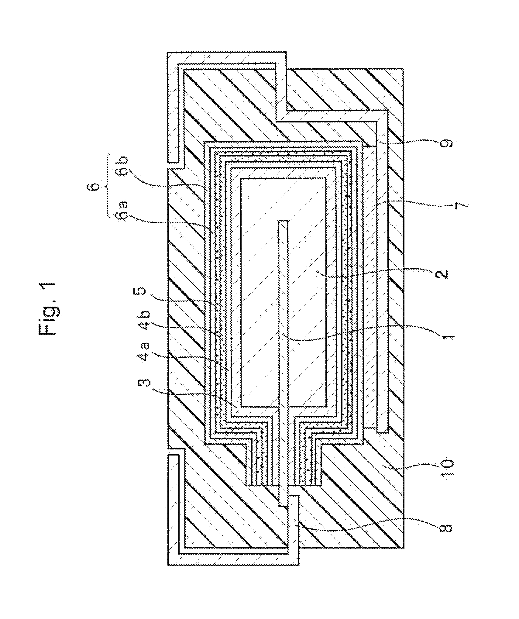
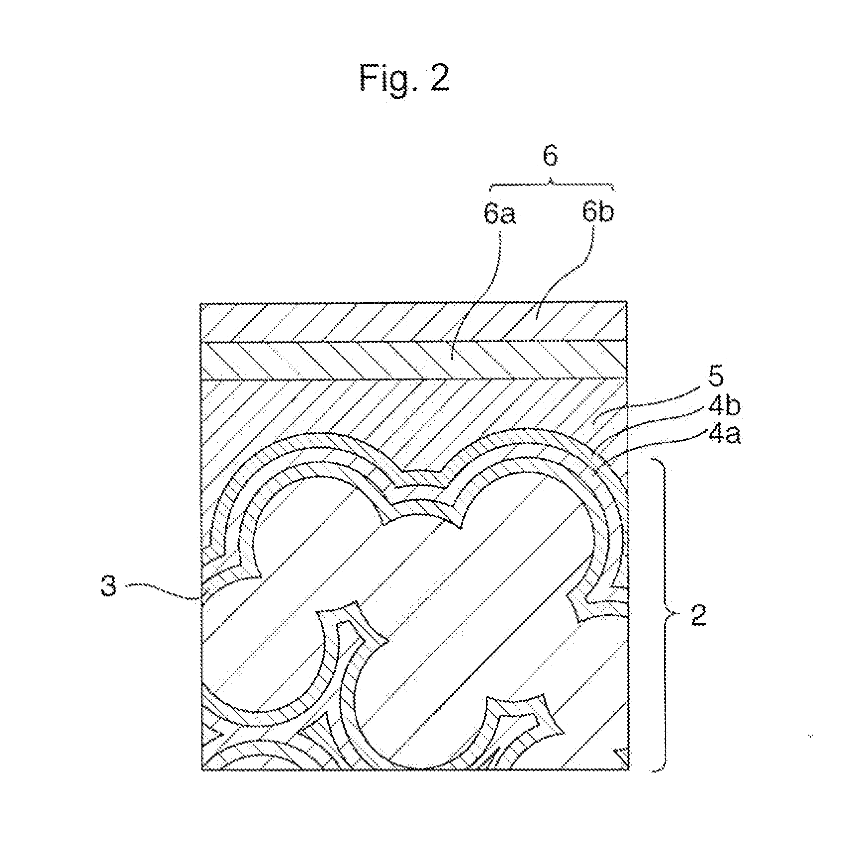
[0063]Metal powder of tantalum is used as the powder of the valve metal. The tantalum powder is formed into a shape while an anode lead made of tantalum is buried in the tantalum powder. Then, the structure thus formed is sintered at approximately 1200° C. in a vacuum atmosphere, and a tantalum sintered-body element to be used as an anode body is thus obtained.

[0064]The surfaces of the tantalum sintered-body element are anodized in a phosphoric acid aqueous solution of 0.05 wt % at a constant voltage of 10 V, and thus a dielectric layer is formed.

Step 2

[0065]Subsequently, the resultant element is dipped in a solution prepared by dissolving polyvinyl alcohol (PVA) in pure water in such a manner that the solution has a PVA concentration of 0.1 wt %. Then, the element is dried to sufficiently remove the solvent, and a first polymer film is thus formed. The work function of the polyvinyl alcohol is measured with a photoelectronic spectrometer, and a value of 6.2 eV is obtained. Th...

example 2

[0071]A solid electrolyte capacitor of Example 2 is fabricated in the same manner as that of Example 1 but with a modification of Step 3 of Example 1 as follows. The element is dipped in a solution prepared by dissolving 9,9-octylfluorene-stilbene-triphenylamine copolymer in toluene in such a manner that the solution has a 9,9-octylfluorene-stilbene-triphenylamine copolymer concentration of 0.1 wt %. Then, the element is dried to sufficiently remove the solvent, and a second polymer film is thus formed. Subsequently, the following steps 4 to 6 are performed in a similar manner to those in Example 1. The work function of the 9,9-octylfluorene-stilbene-triphenylemine copolymer is measured with a photoelectronic spectrometer, and a value of 5.4 eV is obtained. The thickness of the film of 9,9-octylfluorene-stilbene-triphenylamine copolymer is calculated from the concentration and the porosity of the element, and a thickness of 10 nm is obtained.

example 3

[0072]A solid electrolyte capacitor of Example 3 is fabricated in the same manner as that of Example 1 but with a modification of Step 2 of Example 1 as follows. The element is dipped in a solution prepared by dissolving polyethylene glycol (PEG) in pure water in such a manner that the solution has a PEG concentration of 0.1 wt %. Then, the element is dried to sufficiently remove the solvent, and a first polymer film is thus formed. The work function of the polyethylene glycol is measured with a photoelectronic spectrometer, and a value of 6.0 eV is obtained. The thickness of the film of polyethylene glycol (PEG) is calculated from the concentration and the porosity of the element, and a thickness of 10 μm is obtained. Subsequently, the following steps 3 to 6 are performed in a similar manner to those in Example 1.


PUM


Abstract

An aspect of the invention provides a solid electrolyte capacitor that comprises: an anode body; a dielectric layer formed on the surface of the anode body; a first polymer film formed on the dielectric layer and containing a first polymer; a second polymer film formed on the first polymer film and containing a second polymer that is different from the first polymer; a conducting polymer layer formed on the second polymer film and containing a conducting polymer that is different from the second polymer; and a cathode layer formed on the conducting polymer layer, wherein the first polymer film has a larger work function than that of the conducting polymer layer.

Description

CROSS REFERENCE TO RELATED APPLICATIONS[0001]This application claims priority based on 35 USC 119 from prior Japanese Patent Application No. 2010-040677 filed on Feb. 25, 2010, entitled “SOLID ELECTROLYTE CAPACITOR”, the entire contents of which are incorporated herein by referenceBACKGROUND OF THE INVENTION[0002]1. Field of the Invention[0003]The invention relates to a solid electrolyte capacitor using a conducting polymer as an electrolyte layer.[0004]2. Description of Related Art[0005]Solid electrolyte capacitors have wide applications in such various electronic apparatus as personal computers, mobile electronic apparatus, game machines, and servers. The solid electrolyte capacitors are used mainly for the purpose of smoothing the voltage in power supply circuits and removing current noise.[0006]typical electronic apparatus includes plural integrated circuits, such as ICs and LSIs. The operation of each IC or LSI causes instantaneous current flow, resulting in a drop of voltage. ...

Claims


Application Information

Patent Timeline
IPC IPC(8): H01G9/025H01G9/15
CPCH01G9/0036H01G9/15H01G9/0425H01G9/028
Inventor KOMATSU, KEIICHINISHIMURA, KOICHISANO, TAKESHI
Owner SANYO ELECTRIC CO LTD
Why Eureka
Try Eureka