Semiconductor memory device and semiconductor device
a semiconductor memory and semiconductor technology, applied in the field of memory devices, can solve the problems of not meeting all necessary conditions of the semiconductor device, the size of the power supply device needs to be larger, and the device has good and bad points, so as to achieve the effect of small variation in the amount of charge at the time of writing data and reducing the threshold value of the whole semiconductor memory devi
- Summary
- Abstract
- Description
- Claims
- Application Information
AI Technical Summary
Benefits of technology
Problems solved by technology
Method used
Image
Examples
embodiment 1
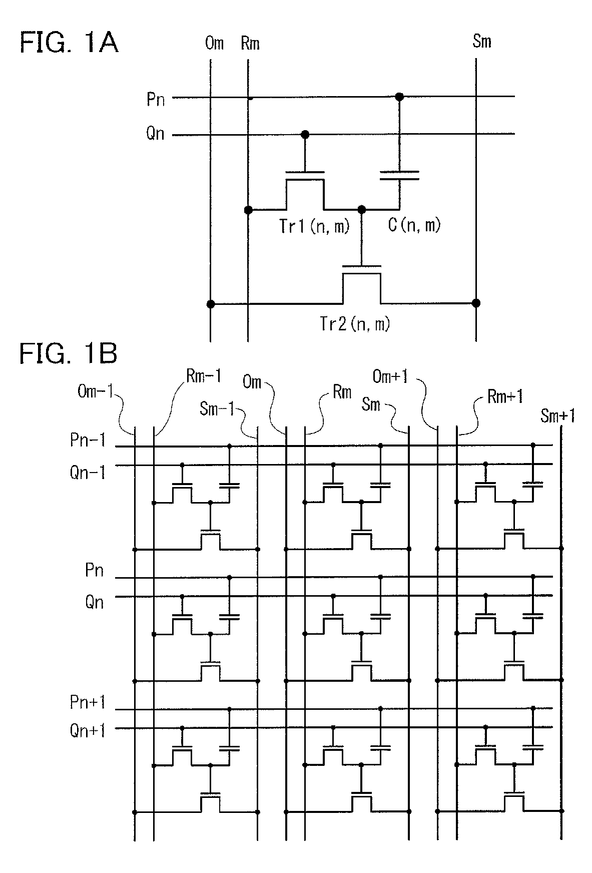
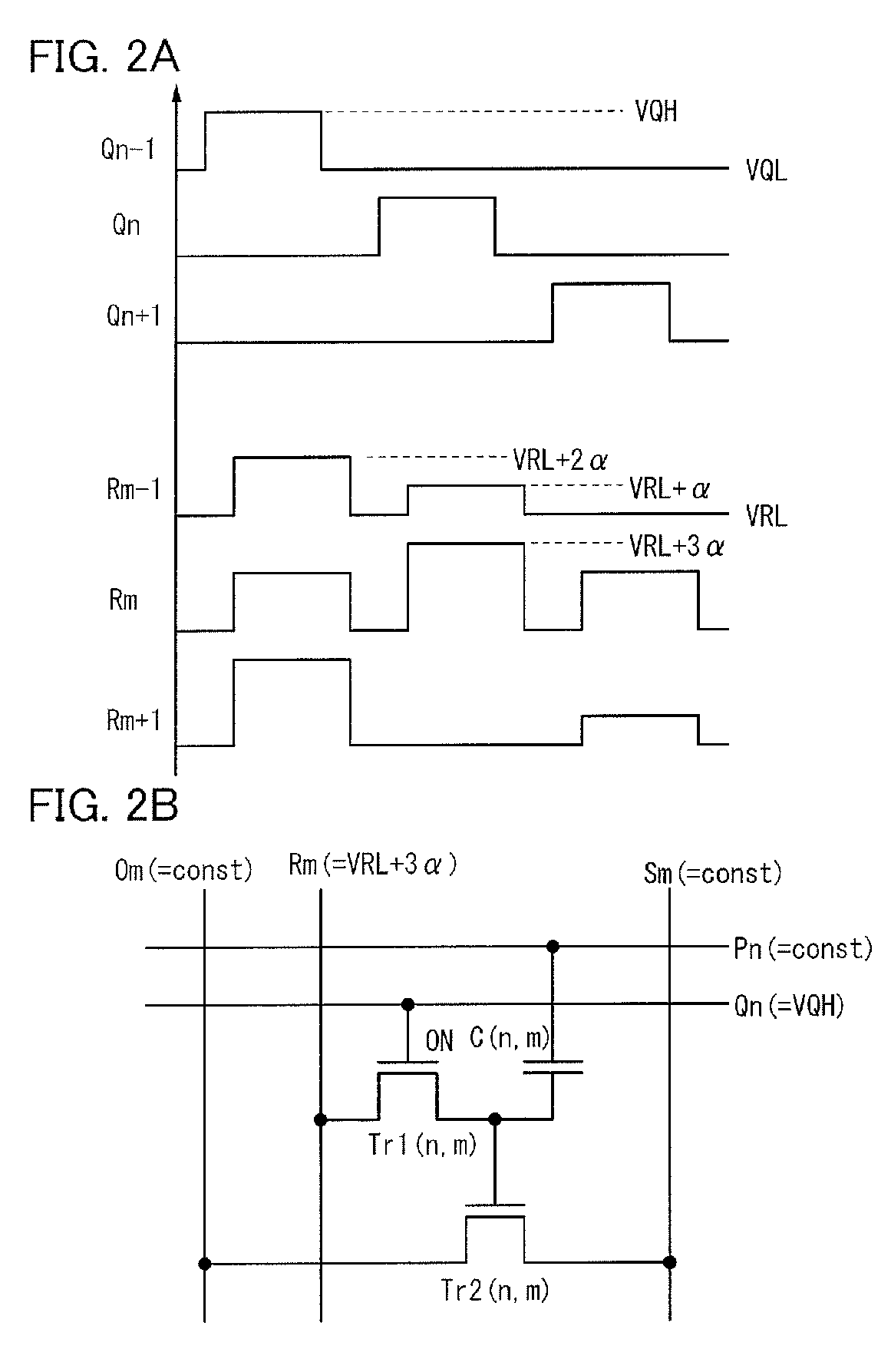
[0095]In this embodiment, operation of a semiconductor memory circuit illustrated in FIGS. 1A and 1B is described. Here, both the writing transistor Tr1 and the reading transistor Tr2 are n-channel transistors. First, a writing method is described with reference to FIGS. 2A and 2B. At the time of writing, the reading bit lines ( . . . , Om−1, Om, Om+1, . . . ), the bias lines ( . . . , Sm−1, Sm, Sm+1, . . . ), and the reading word lines ( . . . , Pn−1, Pn, Pn+1, . . . ) are held at constant potential. Although potential may be different depending on the kind of a wiring, the potential of any wiring is set to 0 volts here.
[0096]In this state, a pulse is sequentially applied to the writing word lines ( . . . , Qn−1, Qn, Qn+1, . . . ) so that the writing transistor is turned on / off. Here, the potential of the writing word line when the pulse is not applied is VQL and potential of the pulse is VQH. As illustrated in FIG. 2A, by sequentially applying the pulse in each row, the writing tr...
embodiment 2
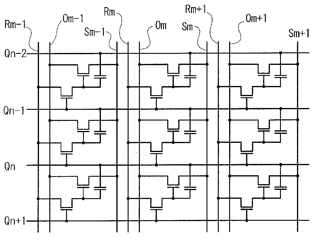
[0109]In this embodiment, operation of a semiconductor memory circuit illustrated in FIGS. 5A and 5B is described. Here, both the writing transistor Tr1 and the reading transistor Tr2 are n-channel transistors. In this embodiment, the reading word line is replaced with the writing word line in another row in Embodiment 1. As described above, by employing this structure, the number of wirings of a semiconductor memory device can be smaller than that in Embodiment 1. In this embodiment, the writing word line in the (n−1)-th row is substituted for the reading word line in the n-th row.
[0110]A writing method is basically the same as the writing method in Embodiment 1. The reading bit lines ( . . . , Om−1, Om, Om+1, . . . ) and the bias lines ( . . . , Sm−1, Sm, Sm+1, . . . ) are held at constant potential. Although the potential may be different between the kinds of wirings, it is desirable that the potential of the reading bit line be equal to that of the bias line in each column in or...
embodiment 3
[0121]In this embodiment, a shape and a manufacturing method of the semiconductor memory device described in Embodiment 2 are described. In this embodiment, an oxide semiconductor containing zinc and indium is used for the writing transistor and a single crystal silicon semiconductor is used for the reading transistor. Therefore, the writing transistor is stacked over the reading transistor.
[0122]That is, an insulated gate transistor using a single crystal silicon semiconductor which is provided over a single crystal silicon substrate is used as the reading transistor and a transistor in which an oxide semiconductor is used for a semiconductor layer is formed thereover as the writing transistor. Note that although an example in which a semiconductor memory device is formed over a single crystal silicon substrate is described in this embodiment, the semiconductor memory device can be provided over another kind of semiconductor substrate or an insulating substrate, alternatively.
[0123...
PUM
 Abstract
Description
Claims
Application Information
 - R&D
- Intellectual Property
- Life Sciences
- Materials
- Tech Scout
- Unparalleled Data Quality
- Higher Quality Content
- 60% Fewer Hallucinations
Browse by: Latest US Patents, China's latest patents, Technical Efficacy Thesaurus, Application Domain, Technology Topic, Popular Technical Reports.
© 2025 PatSnap. All rights reserved.Legal|Privacy policy|Modern Slavery Act Transparency Statement|Sitemap|About US| Contact US: help@patsnap.com


