Radiation therapy system

a radiation therapy and system technology, applied in the field of radiation therapy, can solve the problems of increasing the risk of normal tissue complications, irradiation of healthy tissue, fiducial markers, etc., and achieve the effects of improving the mri image quality, improving the magnetic field strength, and relatively high magnetic flux density of the mri magnet that can be combined with the linear accelerator

Active Publication Date: 2011-09-08
ALBERTA HEALTH SERVICES
View PDF9 Cites 49 Cited by
  • Summary
  • Abstract
  • Description
  • Claims
  • Application Information

AI Technical Summary

Benefits of technology

[0042]A further advantage of the design shown in this disclosure is that, for a practical system the magnetic flux density of the MRI magnet that can be combined with the linear accelerator can be relatively high. This is simply because the direction of electron travel in the linear accelerator is always parallel to the direction of the magnetic field. Thus, the Lorentz force on the electrons is close to or is equal to zero in this case, and no deflections of the electron trajectory are produced by the MRI magnetic field. Thus, if higher magnetic field strengths are required to improve the MRI image quality, the present disclosure can still be used to combine the MRI magnet and the linear accelerator.
[0043]A further advantage of the design shown in this disclosure is that the perturbation of the dose distribution in a patient is more desirable. In some prior proposals, the direction of the x-ray beam is perpendicular to the MICE magnet B0 field. In such cases, the patient dose distribution is perturbed in an undesirable manner, and it can produce considerable hot or cold regions of dose. This effect has been described, for example, in Kirkby et al, Med. Phys. Vol 35, no. 3, pp. 1019-1027, (2008). The effect is directly due to the orientation of the x-ray beam and the direction of the MRI B0 field, and cannot be removed. The effect intensifies at higher magnetic field strengths, and could limit the usefulness of the combined MRI-linear accelerator. However, as described in Bielajew (Med. Phys, vol 20, no. 4, pp 1171-1179 (1993)), when the x-ray beam is in the same direction as an external B field, the lateral electron scatter is reduced. On the central axis of a large field size, Bielajew showed that there is no change to the dose distribution as compared to the zero B field case. On a lateral profile, there will be a change to the dose distribution, since there is reduced lateral electron scattered due to the focusing effect of the Lorentz force. This change results in a sharper dose drop off in the penumbra region, and is thus beneficial in radiotherapy. Thus the dose distribution for the MRI-Linear accelerator system described here will have superior qualities to those in previously disclosed systems.
[0044]Another advantage provided is that due to the focusing of the particles, the dose distribution has a sharper dose drop off in the penumbra region, and thus exhibits improved beam sharpness at the beam edges.
[0045]A further advantage of the design shown in this disclosure is that it allows for a more compact size since the linear accelerator can be placed closer to the MRI magnet isocentre without any added complexity of magnetic shielding. This is a significant advantage since the practical usefulness of the device may otherwise be limited by its size. Firstly, the x-ray dose rate at isocenter is inversely proportional to the square of the distance from the linear accelerator target, and so an increased distance betwe...

Problems solved by technology

Because of the uncertainty in identifying this volume at the time of treatment, and due to unavoidable patient and tumour motion, an enlarged, the PTV is typically irradiated.
Because a volume that is larger than the biological extent of the disease is typically irradiated, there is an increased risk of normal tissue complications due to the unnecessary irradiation of healthy tissue.
However, fiducial markers must be placed using an invasive technique, and are thus less desirable.
IGRT techniques based or x-rays or ultrasound are not ideally suited to IGRT: x-rays suffer from low soft tissue contrast and are not ideally suited to imaging tumours; ultrasound cannot be utilized in all locations of the body.
Finally, x-ray and ultrasound based IGRT techniques are difficult to integrate into a linear accelerator such that they can provide images in any imaging plane in real time at the same moment as the treatment occurs.
As is known, there are several significant technological challenges associated with the integration of a linear accelerator with an MRI device.
A further challenge is due to the pulsed power nature of the linear accelerator.
This would thus interfere with the signals emitted by these nuclei as they relax, and would thus deteriorate the image forming process of the MRI.
A further challenge that exists when integrating an MRI with a medical linear accelerator involves the orientation of the MRI magnet with respect to the accelerating waveguide such that the waveguide can be directed at the patient without obstruction from the magnet.
A further challenge relates to the dose deposition pattern obtained when a patient is exposed to high energy x-ray used in radiotherapy in the presence of a strong magnetic field used far imaging by MRI.
A limitation of this disclosure is the small aperture size in the magnet.
The magnet design is complicated, and involves non-circular and complex coils.
However, this method introduces a...

Method used


Image

  • Radiation therapy system
  • Radiation therapy system
  • Radiation therapy system

Examples


Embodiment Construction

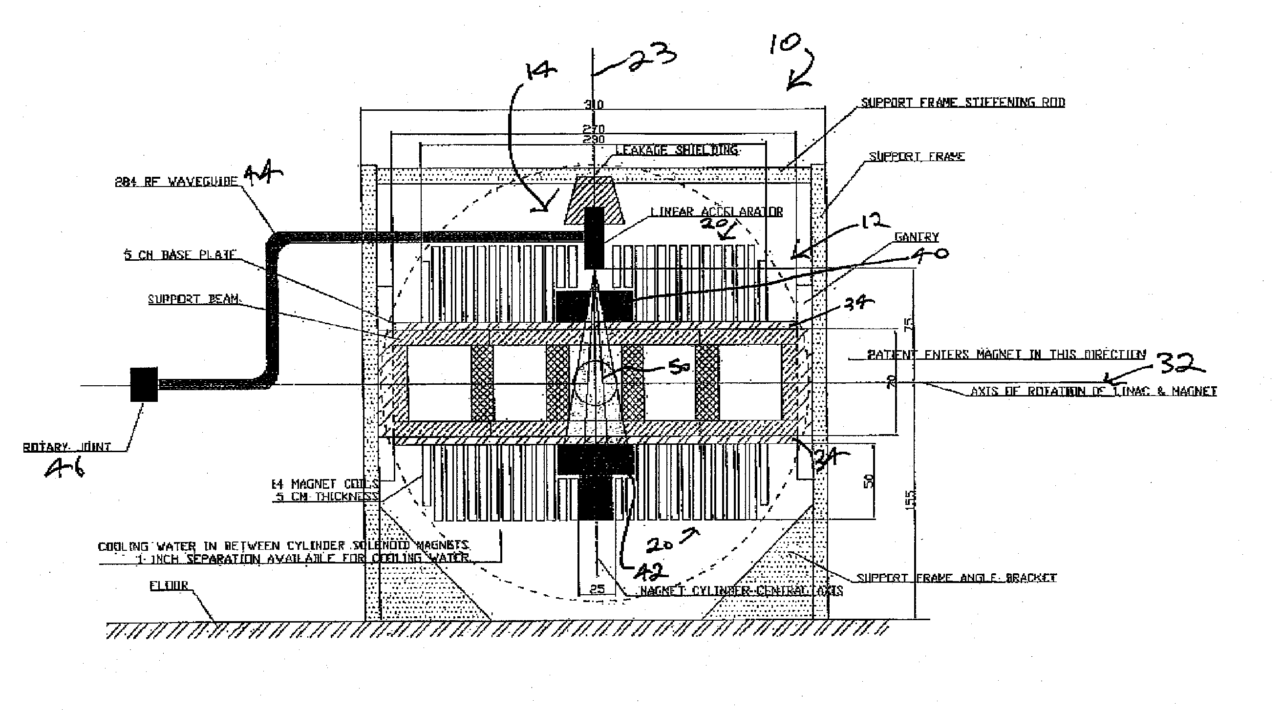
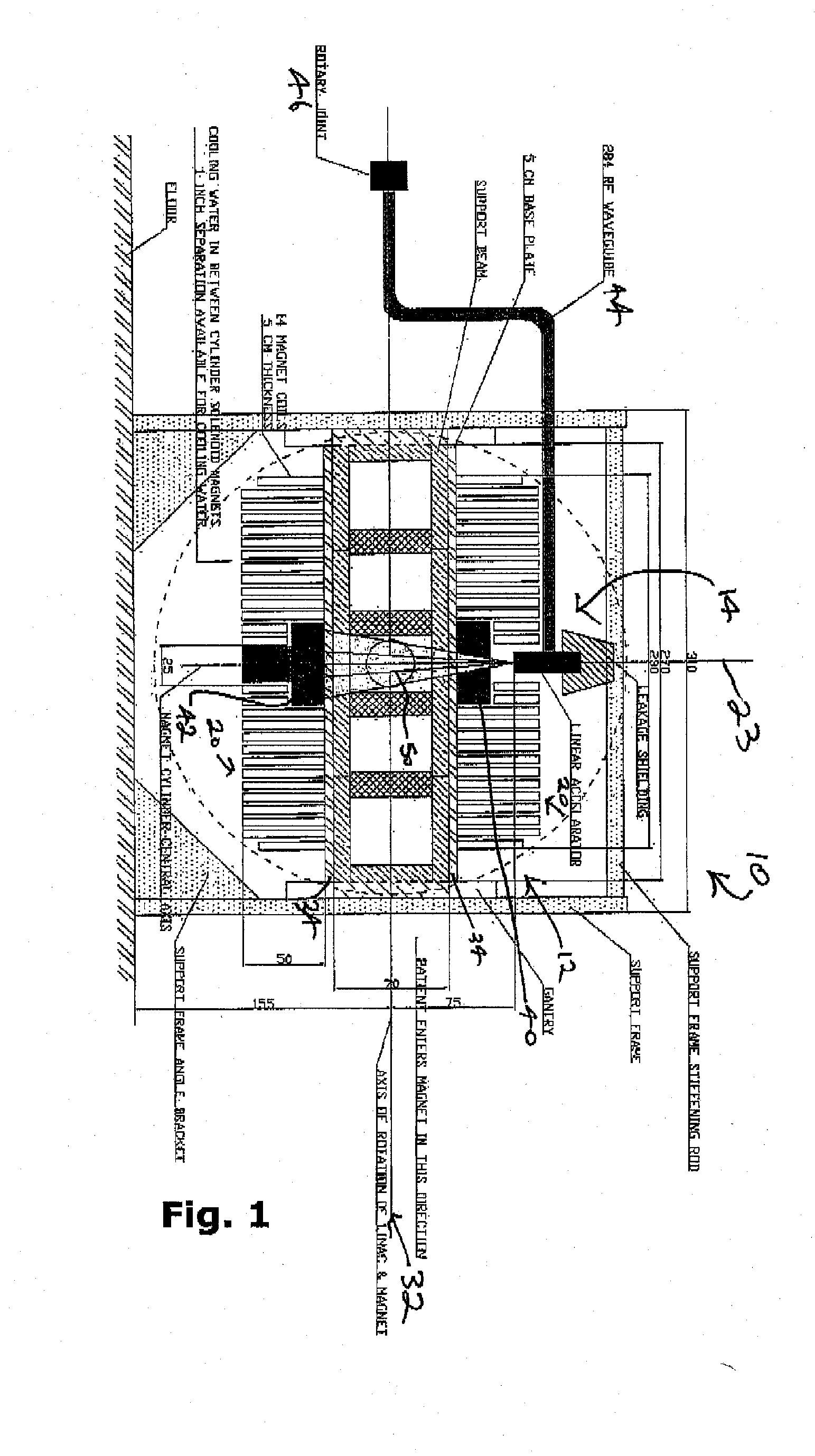
[0053]The present disclosure describes a device which addresses one or more of the problems set out above. In order to reduce the degree to which electrons stray from the central axis of the accelerating waveguide, and to thereby focus electrons on the accelerator's target, a linear accelerator can be immersed in a magnetic field that is parallel to the direction of electron travel in the accelerating waveguide, and advantageously and surprisingly the magnetic field can be provided by the MRI magnet itself.

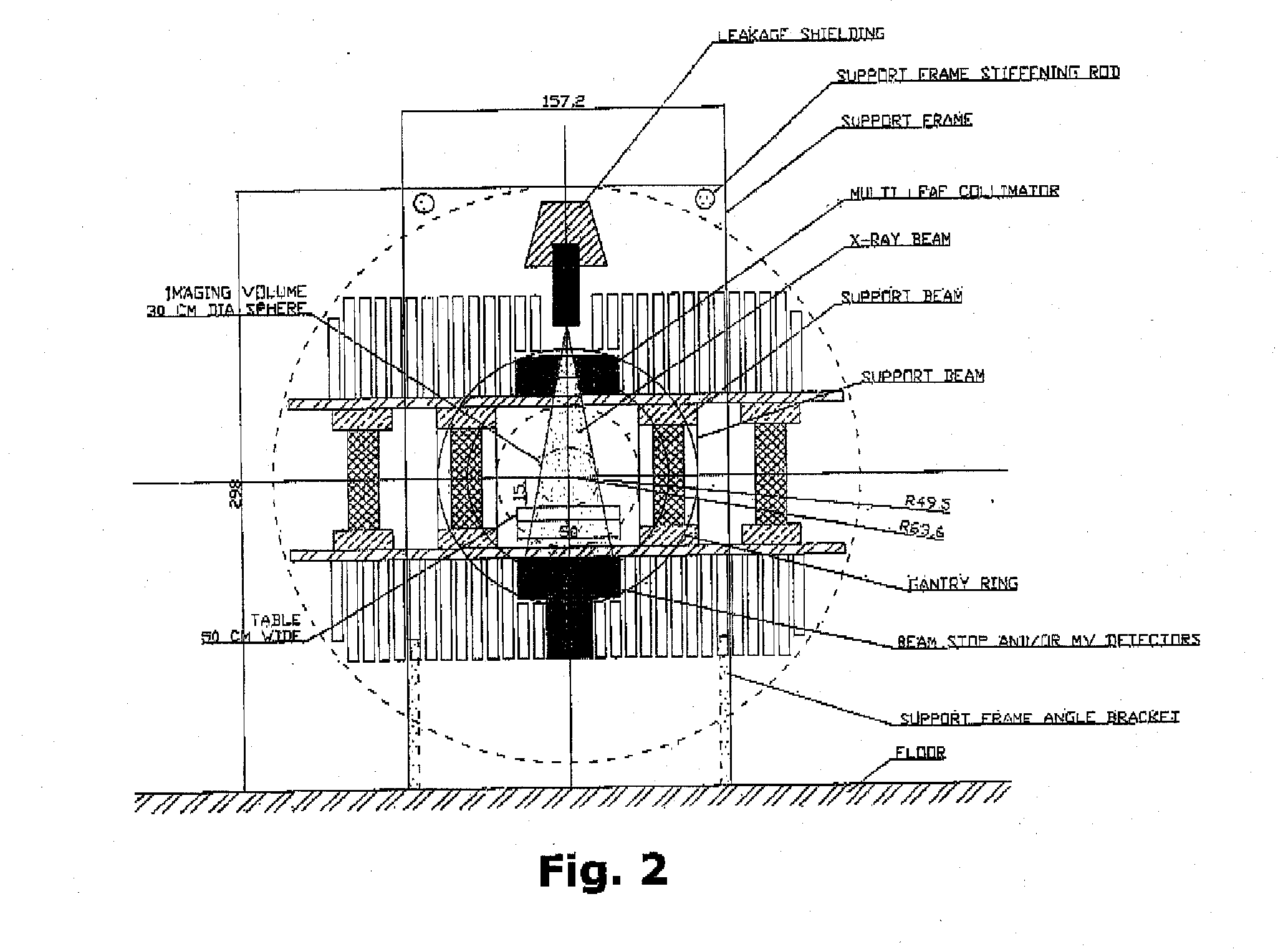
[0054]FIG. 1 is a side view of a radiation therapy system 10 according to an embodiment, that can fit entirely within a room that is three (3) metres in height. Radiation therapy system 10 comprises an open-bore, 0.2 Tesla MRI assembly 12 integrated with a standard S-band standing wave 6 MV linear accelerator 14. Radiation therapy system 10 is configured to provide a 30 cm diameter imaging volume 50, and comprises two sets of fourteen (14) circular coils 20 of different diameters ...


PUM


Abstract

A radiation therapy System comprises a magnetic resonance imaging (MRI) apparatus and a linear accelerator capable of generating a beam of radiation. The linear accelerator is immersed in and oriented with respect to the MRI magnetic field to expose the linear accelerator to magnetic force that directs particles therein along a central axis thereof.

Description

CROSS-REFERENCE TO RELATED APPLICATION[0001]This application claims priority under 35 U.S.C. 119(e) from U.S. Provisional Patent Application Ser. No. 61 / 129,411 filed Jun. 24, 2008, the contents of which are entirely incorporated herein by reference.FIELD OF THE INVENTION[0002]The present invention relates generally to radiation therapy and in particular to a radiation therapy system in which a linear accelerator is immersed in and oriented with respect to the magnetic field of an MRI apparatus to expose the linear accelerator to magnetic force that directs electrons therein along a central axis thereof.BACKGROUND OF THE INVENTION[0003]Image guidance for radiation therapy is an active area of investigation and technology development. Current radiotherapy practice utilizes highly conformal radiation portals that are directed at a precisely defined target region. This target region consists of the Gross Tumour Volume (GTV), the Clinical Target Volume (CTV) and the Planning Target Volu...

Claims


Application Information

Patent Timeline
IPC IPC(8): A61B6/00A61B5/055
CPCA61N5/1049A61N2005/1055Y02E10/38G01R33/4812G01R33/3806Y02E10/30A61B5/055A61N5/1067G01R33/34G01R33/385
Inventor CARLONE, MARCOFALLONE, B. GINOMURRAY, BRAD
Owner ALBERTA HEALTH SERVICES
Why Eureka
Try Eureka