Metal deposition method and laser metal deposition apparatus

a metal deposition apparatus and metal deposition method technology, applied in the direction of soldering apparatus, turbines, manufacturing tools, etc., can solve the problems of generating casting defects, and increasing the possibility of crystals having different crystal orientations, so as to restrict the coarseness of dendri

a metal deposition apparatus and metal deposition method technology, applied in the direction of soldering apparatus, turbines, manufacturing tools, etc., can solve the problems of generating casting defects, and increasing the possibility of crystals having different crystal orientations, so as to restrict the coarseness of dendri

US20110248001A1Inactive Publication Date: 2011-10-13HITACHI LTD

Image

  • Metal deposition method and laser metal deposition apparatus
  • Metal deposition method and laser metal deposition apparatus
  • Metal deposition method and laser metal deposition apparatus

Examples


first embodiment

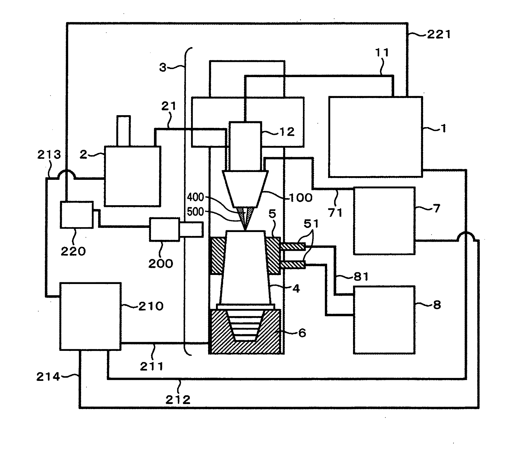
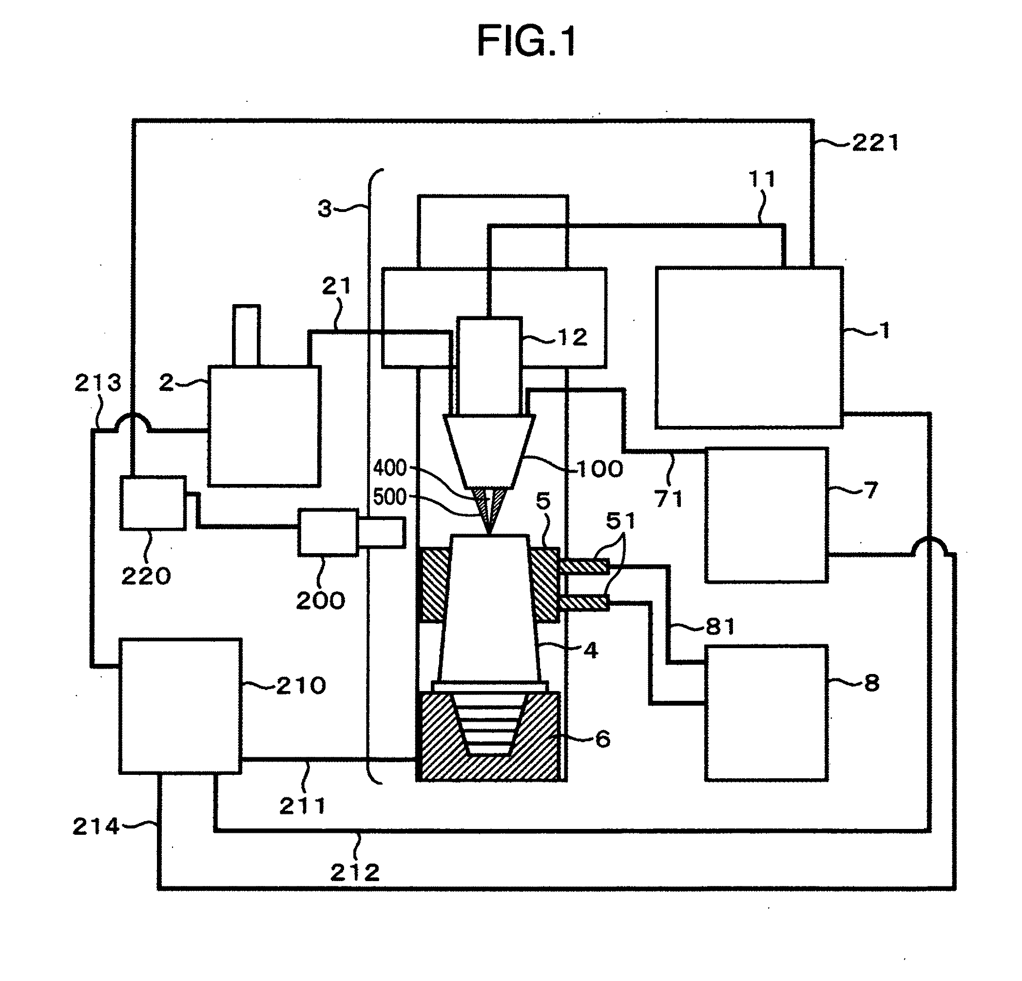
[0023]FIG. 1 shows a laser metal deposition apparatus according to a The reference numeral 1 denotes a laser oscillator, 11 an optical fiber, 12 a laser welding head, 2 a powder feeder, 21 a powder supply pipe, 3 a three dimensional NC processing apparatus, 4 a single crystal alloy bucket (blade), 5 a cooling jig, 51 a refrigerant inlet and outlet, 6 a bucket fixing jig, 7 a gas supply source, 71 a gas supply pipe, 8 a refrigerant supply / circulation / heat exchange apparatus, 81 a refrigerant supply pipe, 100 a powder and shielding gas supply nozzle, 200 a temperature measuring device for a processed portion, 210 a NC control board, 211 a signal conductor to the three dimensional NC processing apparatus, 212 a signal conductor to the laser oscillator, 213 a signal conductor to the powder feeder, 214 a signal conductor to the gas supply source, 220 a controller, which analyzes a temperature signal to command adjustment of laser output, and 221 a laser output adjustment signal conducto...

second embodiment

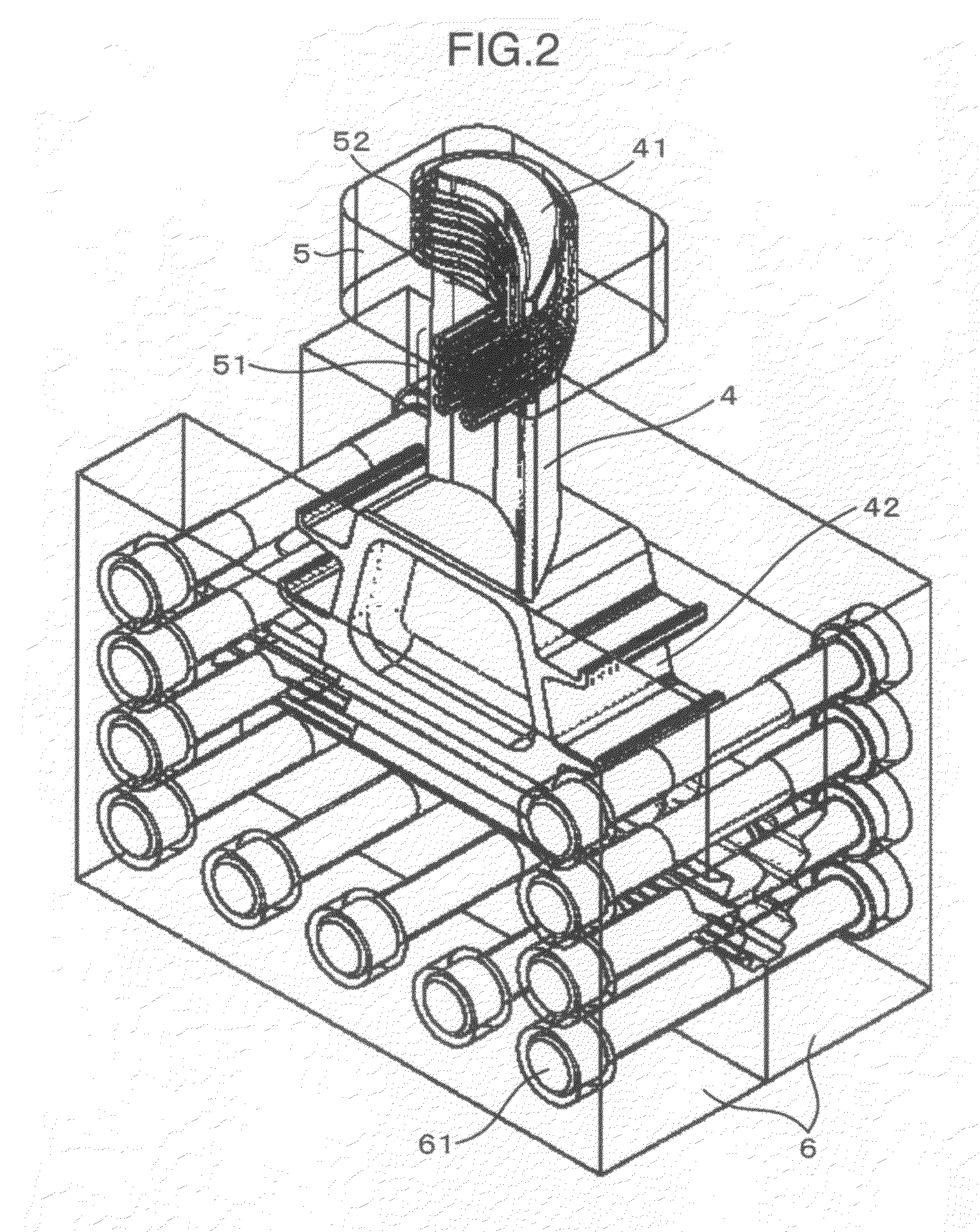
[0030]FIG. 4 shows a method of using the direct cooling jig 9, for forcedly cooling at the time of laser metal deposition welding. The reference numeral 4 denotes the single crystal alloy bucket, 41 the processed surface, 42 the dovetail portion, 9 a direct cooling jig, 91 a refrigerant inlet, 92 a refrigerant jetting flow passage, 93 a refrigerant shielding plate, 51 the refrigerant inlet and outlet, 52 the refrigerant flow passage, 6 the bucket fixing jig, and 61 the connection bolt and nut of the bucket fixing jig. The single crystal alloy bucket 4 is fixed to the bucket fixing jig 6 and the direct cooling jig 9 is mounted on a parent material side from a processed portion to bring the same into close contact with the bucket. Hereupon, when a refrigerant is jetted so as to surround the processed surface, a maximum temperature gradient is generated also in a direction perpendicular to a preferential growth orientation of parent material crystals of the single crystal alloy bucket...


PUM

PropertyMeasurementUnit
temperatureaaaaaaaaaa
heightaaaaaaaaaa
lengthaaaaaaaaaa

Abstract

In a deposition method of forming a buildup on a single crystal or directionally solidified crystal parent material, metal deposition is performed from an extension in a preferential growth orientation of parent material crystals while forcedly cooling a portion of the parent material somewhat below a processed surface and beforehand giving a temperature gradient to the parent material so that a maximum temperature gradient is oriented along the preferential growth orientation of parent material crystals.

Description

BACKGROUND OF THE INVENTION[0001]The present invention relates to a metal deposition method of forming a buildup in buildup welding for alloy products with a crystal orientation thereof controlled, while controlling solidification so as to make a crystal growth orientation of the buildup the same as a solidification crystal orientation of a base material alloy and a laser metal deposition apparatus used therefor.[0002]Large stresses are applied to buckets (blades) of a turbine, a jet engine, etc by centrifugal forces. Therefore, there are used buckets formed from directionally solidified alloys and single crystal alloys, of which a crystal orientation is in a direction, in which centrifugal forces act. Directionally solidified alloy buckets and single crystal alloy buckets suffer oxidation reduced thickness, crack, etc. when used in high temperature and high load environments over a long term. Also, casting defects are generated at the time of manufacture in some cases. Such defects...

Claims


Application Information

Patent Timeline
13 Oct 2011
Publication
US20110248001A1
IPC
B23K9/04; B23K26/00; B23K26/046; B23K26/14; B23K26/34; B23K31/00
CPC
B23K26/1411; B23K26/345; B23K26/3293; B23K2201/001; B23K35/0244; C30B11/00; C30B11/003; C30B11/005
Inventors
KAWANAKA, HIROTSUGU; TSUKAMOTO, TAKESHI