
Composite Thermal Insulation Wall Body of a Building

a technology of composite materials and building walls, applied in the direction of walls, building components, construction, etc., can solve the problems of poor earthquake-proofing and wind-proofing ability, large steel consumption, and insufficient material development, so as to reduce the weight of constructions, good thermal insulation and bonding effects of functional materials, and high performance

Inactive Publication Date: 2011-10-27
WU SHUHUAN
View PDF1 Cites 33 Cited by
  • Summary
  • Abstract
  • Description
  • Claims
  • Application Information

AI Technical Summary

Benefits of technology

[0031]Technical effect of the invention: the composite thermal insulation members of the constructions are bonded with the outer protecting layers on both sides by using the light thermal insulation core layer. There are tension meshes or steel bars inside the outer protecting layers on the outside of the composite thermal insulation member forming light composite thermal insulation member. The invention not only develops the merits of the force-receiving materials, but also ensures the safely of the composite components with good thermal insulation and bonding effects of the functional materials. The light composite thermal insulation member significantly decreases the weight of constructions and can be used in constructions of any height. The invention provides technical support to construction of light wall and roofs with low heat transfer coefficients and quake-proofing as well as wind-proofing. Advanced technique of wall provides high performances, low cost, simple design and convenient construction.
[0032]As comparing with the composite wall of the prior art, the present invention has simple structure, convenient construction, greatly reduces material consumption of steel stainless steel and manpower consumption of installation, greatly decreases construction cost, and provides better force-bearing performance of the composite wall.
[0033]The invention simultaneously satisfies the requirements of wall: light weight, thermal insulation and energy saving, land saving, quake and wind-proofing, safety of outer decoration, fireproofing, duration, low cost, convenient construction.
[0034]The present invention undermines the concept of forming the traditional wall. China encounters many difficulties at energy saving and wall reforming in the past decades, because the wall technology is not only about the new-type wall material alone. Wall technology is a system engineer, which engages multiple disciplines in order to satisfy the various demands of the performance of the wall nowadays.

Problems solved by technology

According to the prior art, the large quantity of steel in the wall with light steel skeletons is located in the middle of the section of the wall without cooperation with the fine stone concrete or cement mortar, so the sectional bend-resisting moment of the skeleton is small, leading to big consumption of steel, but the capability of quake-proofing and wind-proofing is still poor, not fully developing the merit of materials.

Method used


Image

  • Composite Thermal Insulation Wall Body of a Building
  • Composite Thermal Insulation Wall Body of a Building
  • Composite Thermal Insulation Wall Body of a Building

Examples


embodiment 1

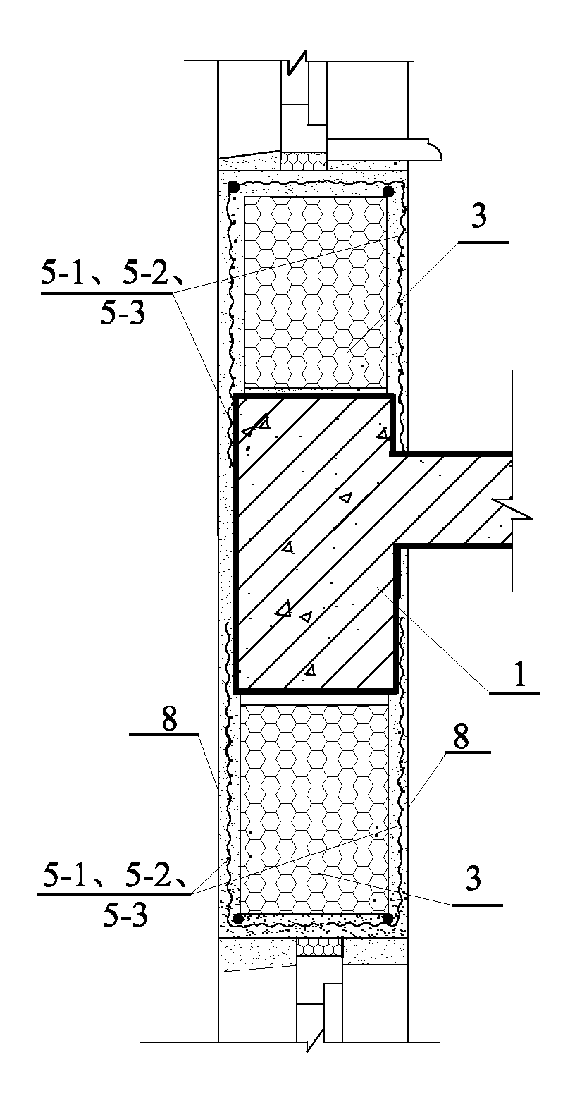
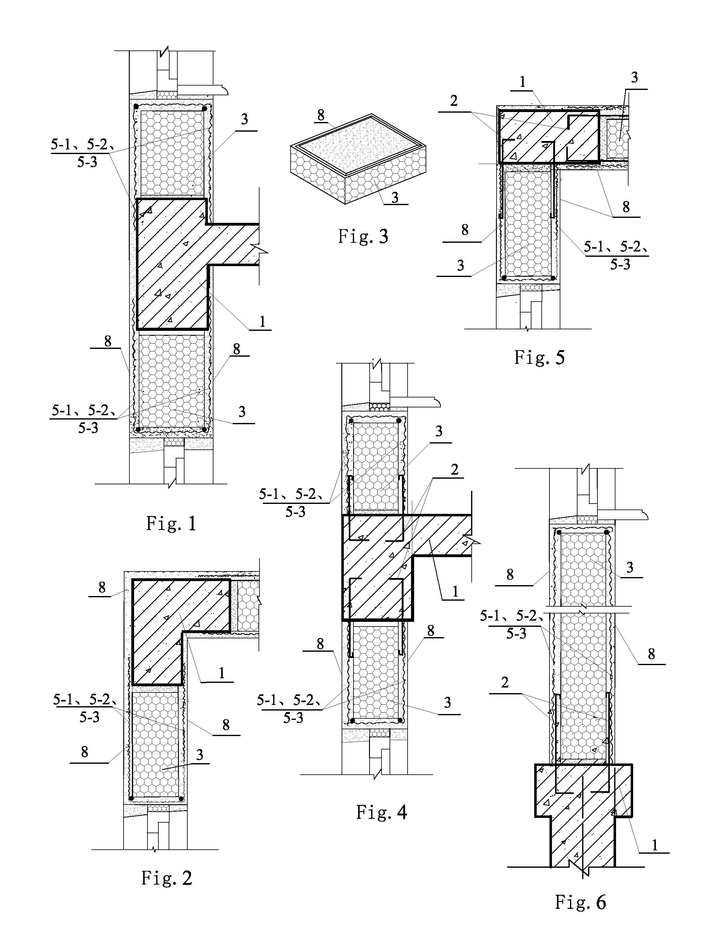
[0073] as shown in FIGS. 1 and 2, a composite thermal insulation component of a building of the embodiment is composed of a load-bearing component 1 of a main structure of the building, a core layer 3, alkali-resistant netting fabric 5-1 or a metal net 5-2 or a bamboo reinforced net 5-3 and an outer protection layer 8. The load-bearing component 1 of the main structure of the building is a girder, a plate, a pillar, a load-bearing wall and a base. The core layer 3 is made of a high molecular thermal insulation material or mineral wool or plant stalks or a paper honeycomb plate. The outer protection layer 8 is a cement mortar, a fine stone concrete plastered layer, a modified cement mortar or a fine stone concrete plastered layer. The said core layer 3 is fixed between the girder or the plate or the pillar of the load-bearing component 1 of the main structure of the building and a interior frame formed by a load-bearing wall, or on the girder or the plate of the load-bearing componen...

embodiment 3

[0079 is suitable for energy-saving buildings. When the composite wall body with outside thermal insulation is constructed, first the core layer is bonded to the outside of the girder-pillar, then the core layer inside the openings of the girder-pillar of the frame is assembled. According to convenience of construction, economic analysis and duration use, the metal net or alkali-resistant netting fabric is determined. The bamboo reinforced net is suitable for simple low-level buildings. Internationally, the results of test of the GRC wall plate used for 25-30 years showed that under the regular condition of indoor use, the strength of the alkali-resistant glass fiber has not been reduced while the strength of that outdoors is reduced. This circumstance becomes more serious at the places more liable to wetting such as windows. Therefore, for the outer wall of design life span over 25 years, besides necessary water-proof measures, it is suitable to provide the steel bars and metal net...

embodiment 8

[0090] the embodiment is different from the preceding embodiment in that the core layer 3 of the composite wall body plastered by the alkali-resistant netting fabric of the embodiment has T-shaped section, which is beneficial to increase the plane rigidity of the composite wall body.

[0091]In the case of using Embodiment 1 or 2 in the load-carrying light composite wall body (the core layer is fixed on the girder or plate of the load-carrying component with the upper part provided with the light roof) sometimes the structures of Embodiment 7 or 8 are needed.

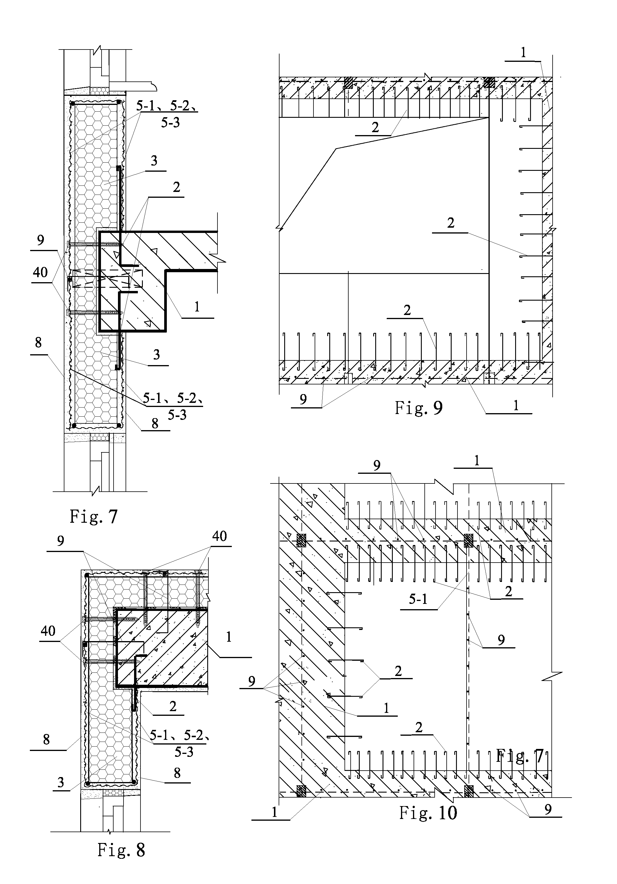
[0092]Embodiment 9: as shown in FIGS. 7 and 8, the embodiment is different from Embodiment 3 in that plastic expansion nails 40 are fixed to the load-carrying component 1 of the main structure of the building through the core layer 3. The iron wires are banded to the outer ends of the tubes of the plastic expansion nails fixing the alkali-resistant netting fabric 5-1 or steel mesh 5-2 or bamboo-reinforced screen 5-3 and the plastic...


PUM


Abstract

A composite thermal insulation member of building is provided. It relates to the composite thermal insulation member of the building, especially the composite thermal insulation wall body and the composite roof aimed to solve the problem of high cost of the existing energy-saving wall body and the inconvenience of construction, the first structure is the core layer bonded inside the frame with the outer protecting layer provided on the surface of the core layer and the alkali-resistant netting fabric bonded to the outer protecting layer and the load-carrying component, the second structure is the core layer provided between the indoor and outdoor outer protecting layers and bonded each other, also the steel hoop fixed with the steel bars inside the indoor and outdoor outer protecting layers, the third structure is the outer protecting layer provided on two sides of the core layer and its upper side and bonded to it, also the core layer and the steel bars arranged inside the outer protecting layer as well as the outer protecting layer wrapped and surrounded by the alkali-resistant netting fabric, the fourth structure is the composite pillar anchored to the main structure and the core layer bonded to the main structure and the light composite pillar with the composite girder supported on the composite pillar and the plastered outer protecting layer on the composite pillar, composite girder and the outer side of the core layer, the fifth structure is the core layer provided between the upper and lower outer protecting layers with the lower outer protecting layer fixed to the girder or wall of the main structure, the invention has the advantages of low cost, convenience of construction etc. which is beneficial to the energy-saving of the construction and the reform of the wall body.

Description

BACKGROUND OF THE PRESENT INVENTION[0001]1. Field of Invention[0002]The invention is related to a composite thermal insulation member of buildings, in particular a light composite thermal insulation wall with thermal insulation properties and a light composite thermal insulation roof.[0003]2. Description of Related Arts[0004]Currently, the widely used thermal insulation wall in China is made of EPS (expandable polystyrene) board and covered by plaster, which has poor fireproof performance and short life duration. In USA and Russia, the widely used 2+3 layers sandwiched thermal insulation wall structure has the problems of thick wall, causing the waste of lands, and also is not suitable for high rise buildings. Additionally, the thermal insulation walls constructed of wood are not practical in the countries where wood resources are scarce, and also have poor wind-proof properties.[0005]The outer walls made of aerated concrete or light hollow blocks are mostly used in China. However, ...

Claims


Application Information

Patent Timeline
Patent Type & Authority Applications(United States)
IPC IPC(8): E04C2/288
CPCE04B1/14E04B1/20E04B1/76E04B1/78E04C2/288E04B2/845E04B2/847E04B2001/7679E04B2/562
Inventor WU, SHUHUAN
Owner WU SHUHUAN
Learn More