Well Flaw Detection System (Embodiments)

a technology of well flaws and embodges, which is applied in the field of well flaw detection systems, can solve the problems of increasing the water cut in the produced fluid, increasing the service life of low-time-consuming well repairs, and not being suitable for non-conductive materials, etc., and achieves high detection efficiency and high temperature

Active Publication Date: 2011-11-24
SCHLUMBERGER TECH CORP
View PDF7 Cites 35 Cited by
  • Summary
  • Abstract
  • Description
  • Claims
  • Application Information

AI Technical Summary

Benefits of technology

[0011]This invention is intended for downhole geophysical inspection, more specifically, provides equipment for flaw detection in casing strings and cement bond quality control using a radiographic device comprising high pressure gas filled gamma detectors. These detectors have high detection efficiency and can be operated at high temperatures.

Problems solved by technology

On the other hand, low time consuming well repairs largely increase well service life.
Flaws and cavities in the cement due to low quality cementing may cause water cut increasing in the produced fluid because water may transfer between formations through holes in the cement.
Obviously, such devices are not suitable for nonconductive materials and hence for cement quality control.
Moreover, these devices do not provide flaw location data if the well has multiple casing strings.
Microscopic flaws or cavities in the hardened cement increase the signal amplitude.
Inaccurate device centering causes phase shift between signals.
However, the necessity to use a large number of crystal detectors (with a photomultiplier tube in each detector) makes this equipment expansive and complex.
Second, the azimuthal resolution is limited by the number of detectors.
Moreover, devices of this type in which NaI crystals are used cannot be operated in hot wells: the normal maximum operation temperature of these devices is about 120° C.
However, a Xe filled detector consisting of multiple cells cannot be used for the angular scanning of pipe shaped articles, but only for the control of flat surfaces with a parallel beam of gamma radiation.
This equipment has too large dimensions and cannot be used as a downhole tool.
However, this device is not suitable for downhole operation as the semiconductor detector can only work at low temperatures and the device has large dimensions.

Method used


Image

  • Well Flaw Detection System (Embodiments)
  • Well Flaw Detection System (Embodiments)
  • Well Flaw Detection System (Embodiments)

Examples


embodiment 1

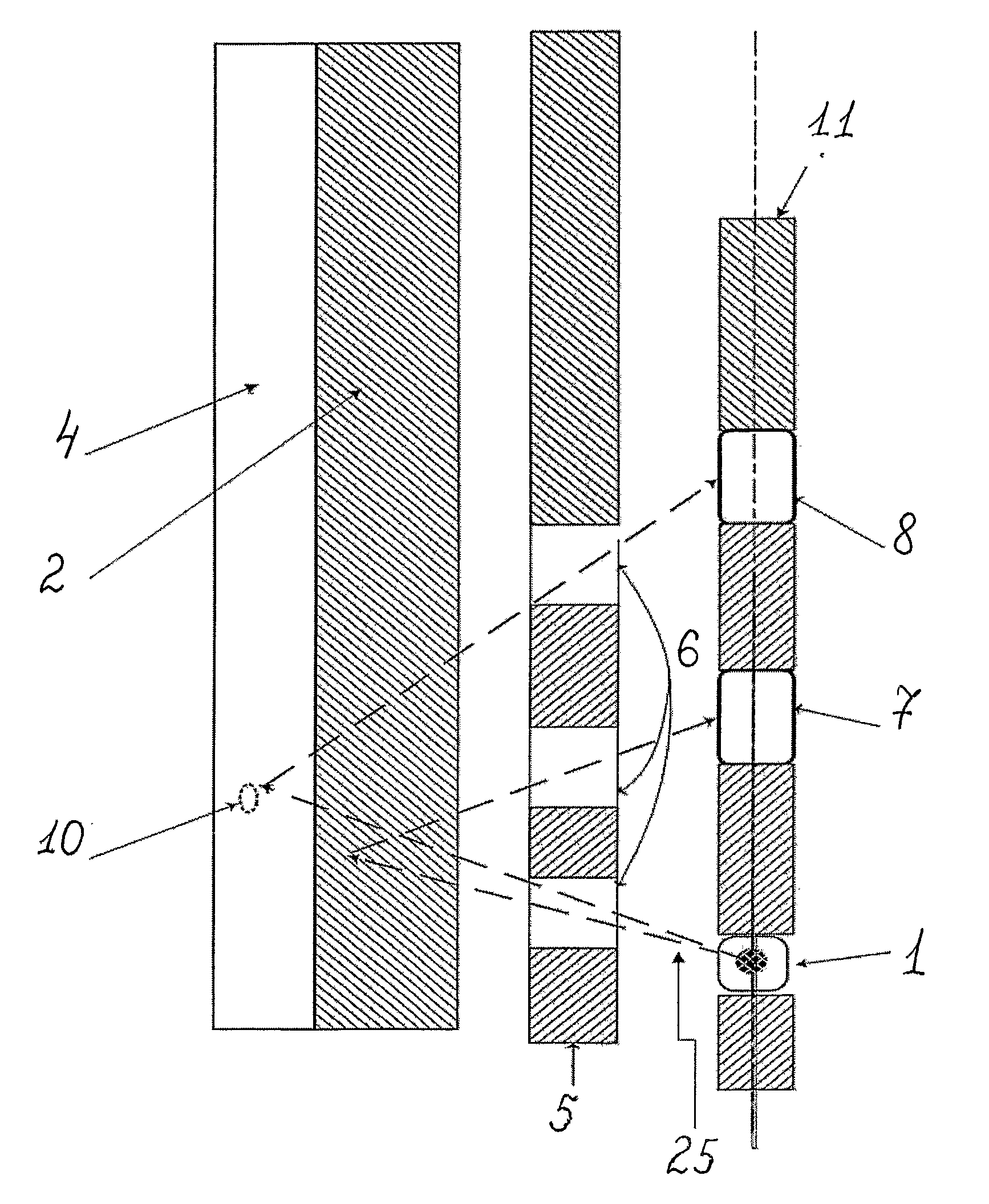
[0015]The set of scintillation detectors (to 12 as in known inventions, e.g. SGDT-100) is replaced for two gas filled detectors (operating in ionization or proportional mode). The two independent gas filled detector's are at a certain distance from the radiation source to allow simultaneous casing string condition and cement quality control. Possible design of the device is shown in FIG. 1. Gamma rays 25 are emitted from the gamma source 1 scattered in the casing string 2 or cement 4, pass through the window 6 of the collimator 5 and are incident upon the detectors 7 and 8 which are coaxial with the gamma source 1. The detectors 7 and 8 are separated by the collimator 11. If the background gamma radiation scattered outside the casing string is low enough (this can be achieved by correctly choosing the collimator shape), the total count rate of the detector 7 gives information on the casing string thickness. The smaller the effective thickness of the string (if the string has a cavit...

embodiment 2

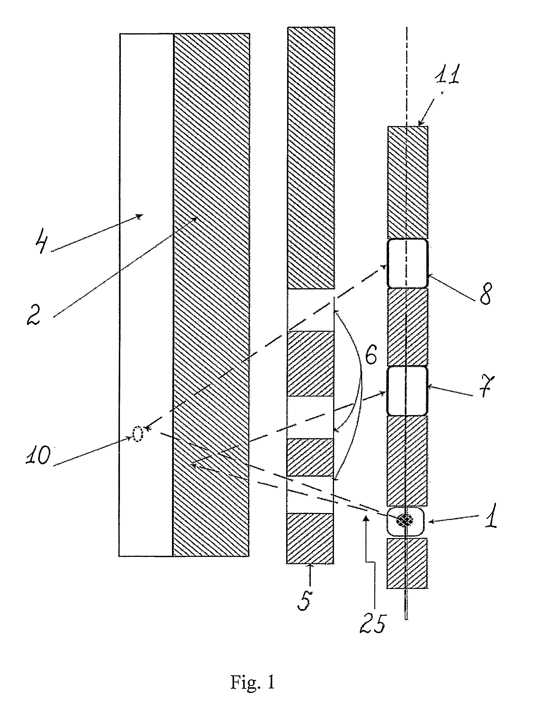
[0016]The number of the detectors can be increased if the task is to obtain further information, e.g. providing the nondestructive control of wells with multiple casing strings. The device operation principle is the same as described above. The design of the device is shown in FIG. 2. The device comprises a gamma source 1, three detectors 7-9, the window 6 of a collimator 5, the collimator 11 for the detectors, two casing strings 2 and 3 and bonding cement 4. In this embodiment the detectors 7 and 8 detect gamma radiation scattered in the casing strings 2 and 3, respectively, and the detector 9 detects gamma radiation scattered in the bonding cement 4. The device performance is limited primarily by gamma radiation attenuation in the casing strings and in the bonding cement, therefore to control cement quality one should either increase the exposure or replace the gamma source (by either increasing the radiation intensity or using gamma source with higher gamma rays energy, e.g. repl...

embodiment 3

[0021]Ionization operation mode is suggested as a preferred embodiment of a gamma ray flaw detector with high pressure gas filled detectors. Operation in this mode requires high density (pressure) media with low near-electrode electric field strength not generating avalanche.

[0022]The high pressure (30-60 bars) Xe filled ionization chamber can be used for flaw detection in the casing string or the bonding cement. High detection efficiency requires high gas pressure which is nearly proportional to gas density. The efficiency of an ionization chamber can be increased by using a Frisch grid; alternatively, only the electron component of the total signal can be used. Possible ionization chamber design is shown in FIG. 3 (plan view). It comprises a light metal cathode 12. For low energy gamma radiation, aluminum or beryllium alloys can be used, whereas for higher energy gamma rays (E>100 keV), stainless steel or a combination of a metal and a nonconductive material with a low attenuation...


PUM


Abstract

This invention relates to nondestructive control, more specifically, to the detection of cracks, flaws and other defects in oil and gas wells and cementing quality control.

Description

PRIOR ART[0001]The detection of cracks, flaws and other defects in oil and gas wells using nondestructive control methods is an ultimate importance task. Timely detection of corrosion, erosion, cracks and other defects of the casing string allows avoiding long downtime periods of production wells. On the other hand, low time consuming well repairs largely increase well service life. Another important task of nondestructive well control is cementing quality control. Flaws and cavities in the cement due to low quality cementing may cause water cut increasing in the produced fluid because water may transfer between formations through holes in the cement.[0002]There are various methods and devices for flaw detection in cased wells and for cement quality control. These devices can be divided into the following categories: electromagnetic devices, sonic and ultrasonic acoustic logging devices and radiographic devices.[0003]Electromagnetic devices use multiple electromagnetic coils some of...

Claims


Application Information

Patent Timeline
Patent Type & Authority Applications(United States)
IPC IPC(8): G01V5/12G01V5/08E21B47/00E21B47/10
CPCE21B47/0005G01V5/125E21B47/1015E21B47/005E21B47/11E21B47/111
Inventor KORKIN, ROMAN VLADIMIROVICHVIKTOROVICH, VIACHESLAV
Owner SCHLUMBERGER TECH CORP
Why Eureka
Try Eureka