Microbial fuel cell and membrane cassette for microbial fuel cells

a fuel cell and membrane technology, applied in the direction of fuel cells, solid electrolyte fuel cells, electrical equipment, etc., can solve the problem of low energy-recovery efficiency as a whol

Inactive Publication Date: 2012-01-05
KAJIMA CORP
View PDF0 Cites 17 Cited by
  • Summary
  • Abstract
  • Description
  • Claims
  • Application Information

AI Technical Summary

Benefits of technology

[0023]With the present invention, the anode (10) is dipped in the liquid containing organic substances (S) while holding anaerobic microorganisms (11), and the cathode (15) is inserted into the liquid (S), wherein the cathode (15) is either enclosed with electrolyte (D) in the airtight hollow cassette (20) having inlet and outlet holes (22, 23) and outer shell 25 of which at least a par

Problems solved by technology

However, such two-step energy recovering system causes loss of energy in the first s

Method used


Image

  • Microbial fuel cell and membrane cassette for microbial fuel cells
  • Microbial fuel cell and membrane cassette for microbial fuel cells
  • Microbial fuel cell and membrane cassette for microbial fuel cells

Examples


experimental example 1

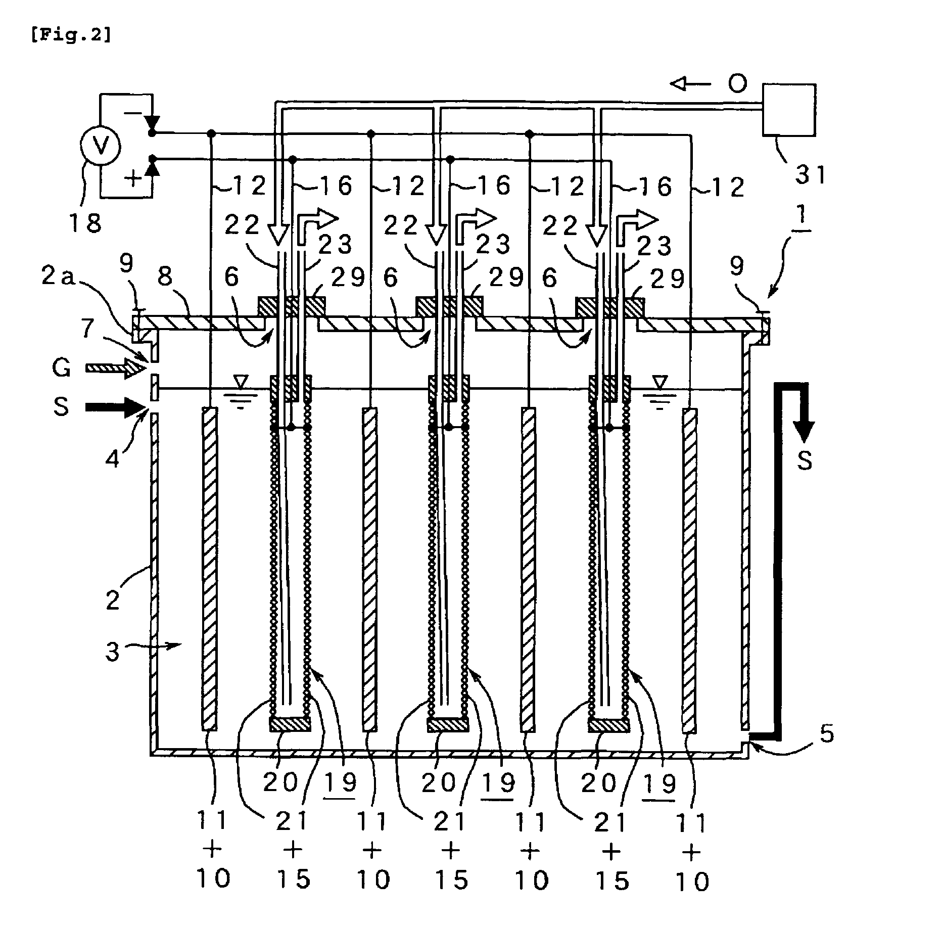
[0041]For the purpose of confirming efficacy of the microbial fuel cell 1 and cassette type diaphragm 19 of the present invention, the microbial fuel cell 1 was test-manufactured by using an anaerobic electrolysis tank 2 (capacity of three liters) of circular section as shown in FIG. 8, an anode 10 made of carbon felt (approx 50 mm×200 mm) as shown in FIG. 3(C), and “air-cathode” as shown in FIG. 3(B), namely an airtight hollow cassette 20 comprising a shell frame 25 (approx 50 mm×200 mm) having a pair of windows 26, 26 (cross section approx 40 mm×180 mm) with stretching MEA (15+21) on both sides, in which five anodes 10 and five air-cathode 20 were arranged facing each other in a radial pattern around the center of them as shown FIG. 8. The tank 2 was continuously fed with artificial wastewater S containing organic polymers including starch (fluid containing organic substance S) at the predefined load of COD (1-3 kg / m3 / day) for 160 days continuously, and voltage was continuously re...

experimental example 2

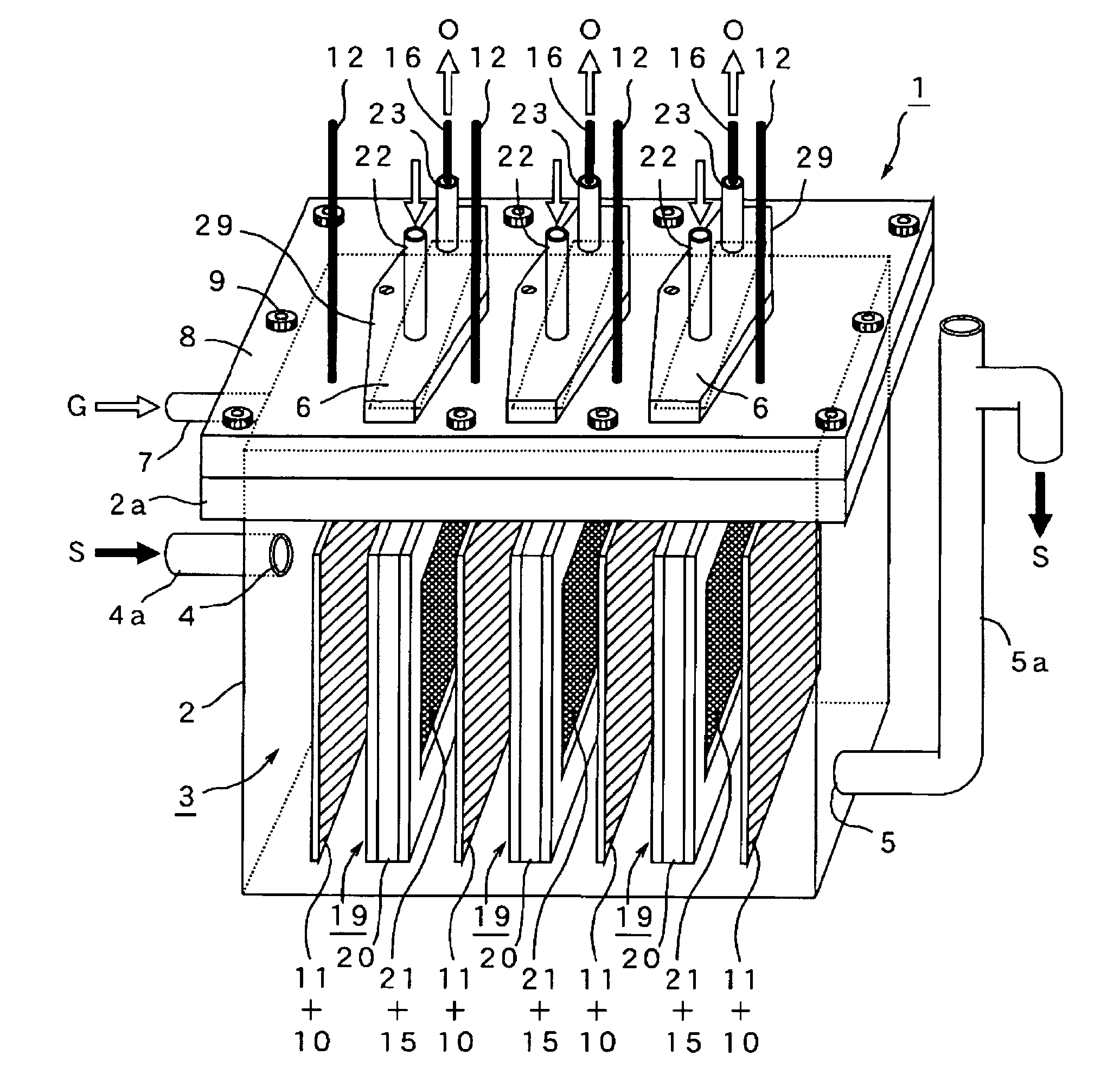
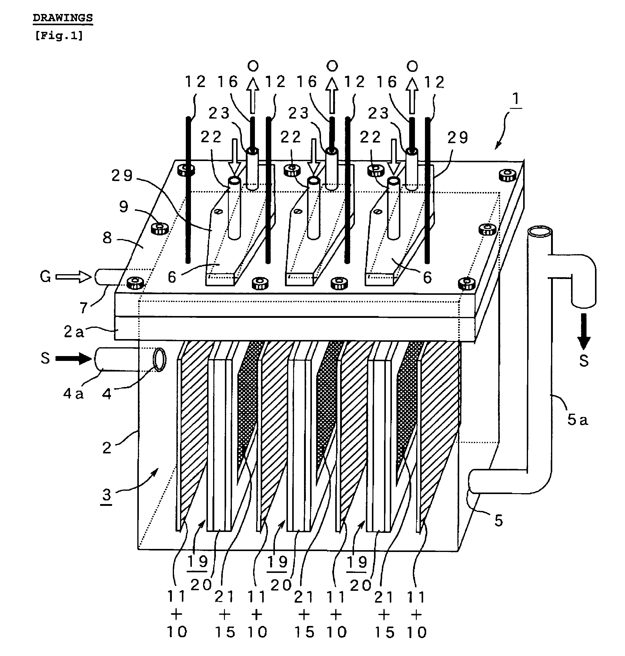
[0043]After 100 days of continuous experiment using the same microbial fuel cell 1 and organic substance S as used in Experimental 1, the microbial fuel cell 1 was disassembled on the 101th day, and exchanged the airtight hollow cassette 20 in the condition that the anode 10 is exposed to air. In this experiment, the tank lid 8 was removed from the anaerobic electrolysis tank 2 by loosing bolts 9 on it (see FIGS. 1 and 2), the five degraded cassettes 20 were pulled out of the each slot 6 while remaining the inside space 3 in the electrolysis tank exposed to air, and then put in the five new cassettes 20 and covered the tank 2 and fastened the bolts 9. Result of this experiment is shown in FIG. 10 indicating that microorganism inhabiting on the anode 10 was damaged during change of the diaphragm 21 under a condition that the anode 10 is exposed to air and voltage recovered at the external electric circuit 18 decreased significantly. It also indicates that it takes another 25 days for...

experimental example 3

[0044]Using the same microbial fuel cell 1 and the fluid containing organic substance S as used in Experiment 1, another long-term continuous experimental operation was conducted. On the 101th day of the experiment, the airtight hollow cassettes 20 were exchanged by pulling out of the cassette slot 6 on the anaerobic electrolysis tank 2 without removal of the tank lid 8. Five slots 6 corresponding to each cassette 20 were built on the anaerobic electrolysis tank 2 which were released temporarily in rotation, and each cassette 20 were quickly replaced with new one. The anode 10 was kept in the liquid containing organic substance S for avoiding exposure to air as much as possible. FIG. 11 shows a result of this experiment, i.e. a chart of voltage variation with time in 180 days.

[0045]The chart of FIG. 11 shows that, when the cassette 20 is exchanged by using closable slot 6, voltage decreased a bit due probably to the effect of a small amount of air inflow and mixing within the anaero...


PUM


Abstract

[PROBLEMS] To provide a microbial fuel cell whose parts can be replaced without lowering the energy recovery efficiency and a membrane cassette for microbial fuel cells. [MEANS FOR SOLVING PROBLEMS] A negative electrode (10) supporting anaerobic microorganisms (11) is immersed in an organic substrate (S). A positive electrode (15) sealed together with an electrolyte (D) in a closed hollow cassette (20) having an outer shell (25) at least a part of which is formed of an ion-permeable membrane (21), an inlet (22), and an outlet (23) or connected to the inner side of an ion-permeable membrane (21) is inserted into the organic substrate (S). While oxygen (O) is supplied into the cassette (20) through the inlet (22) and the outlet (23), electricity is taken out through a circuit (18) electrically interconnecting the negative and positive electrodes (10, 15). Preferably, the outer shell (25) of the closed hollow cassette (20) is a hollow outer shell frame (25) having an opening (26) which is closed by stretching an ion-permeable membrane (21), an inlet (22), and an outlet (23), and the ion-permeable membrane (21) is a membrane/electrode assembly (MEA) formed integrally with the positive electrode (15).

Description

TECHNICAL FIELD[0001]This invention relates to microbial fuel cell and cassette type diaphragm therefor, more specifically microbial fuel cell for generating electricity from liquid containing organic substances by using anaerobic microorganisms and cassette type diaphragm for such microbial fuel cell.BACKGROUND ART[0002]As disclosed in the under-mentioned Patent Documents Nos. 1 and 2, a energy generating or recovering system from organic substances, e.g. organic waste or organic drainage, by using anaerobic microorganisms has been developed, in which the organic substances are converted into biogas such as methane or hydrogen by means of anaerobic microorganisms such as methane fermentation microorganisms or micro-flora, and then the biogas is converted into energy power such as electrical energy by means of turbines or fuel cells. For example, the Patent Document No. 1 discloses a two-step energy recovering system from the organic substances that comprising (i) first step for fee...

Claims


Application Information

Patent Timeline
IPC IPC(8): H01M8/16H01M8/04H01M8/10
CPCY02E60/527H01M8/16Y02E60/50
Inventor YAMAZAWA, AKIRAUENO, YOSHIYUKITATARA, MASAHIROKITAJIMA, YOJIWATANABE, KAZUYASHIMOYAMA, TAKEFUMIISHII, TOSHIKAZUKOMUKAI, SHOKO
Owner KAJIMA CORP
Why Eureka
Try Eureka