Eureka AIR delivers breakthrough ideas for toughest innovation challenges, trusted by R&D personnel around the world.

Dye-sensitized solar cell

a solar cell, dye-sensitized technology, applied in the direction of light-sensitive devices, solid-state devices, electrolytic capacitors, etc., can solve the problems of poor durability of dye-sensitized solar cells of this type, polar structure of dye-sensitized solar cells, and inability to prevent leakage of electrolyte solution and absorption of external moisture, etc., to achieve excellent photoelectric conversion efficiency, less expensive, and light weight

Inactive Publication Date: 2012-01-26
NITTO DENKO CORP
View PDF10 Cites 4 Cited by
  • Summary
  • Abstract
  • Description
  • Claims
  • Application Information

AI Technical Summary

Benefits of technology

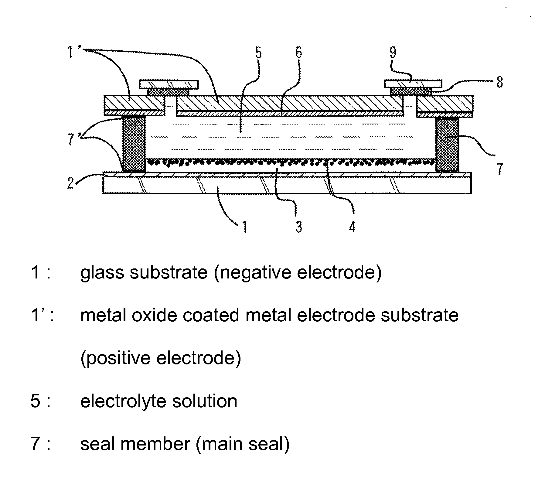
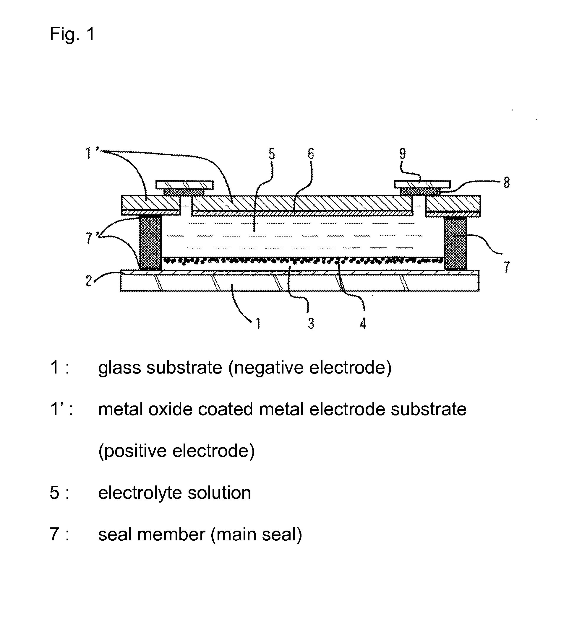
[0012]Photopolymerizable resin compositions containing a photopolymerizable resin as an effective component are useful as a sealing material. The specific photopolymerizable composition described above is particularly effective as the sealing material among the photopolymerizable resin compositions. Further, where the specific surface coating treatment is performed on the portions of the electrode substrates to be brought into contact with the seal member and the metal electrode substrate coated with the metal oxide film is used as one of the paired electrode substrates, the metal oxide film effectively forms chemical bonds with the silane coupling agent of the (meth)acryloxyalkylsilane by a reaction with an alkoxy group of the silane coupling agent, and this is essential for effective sealing.
[0021]Where the photopolymerizable composition (A) contains a poly(meth)acrylate compound in addition to the hydrogenated elastomer derivative, the crosslinking density of the material for the seal member is increased. Therefore, the seal member is further excellent in durability and, when a photopolymerization initiator is used, the curability with ultraviolet (UV) radiation is improved.

Problems solved by technology

However, if a conventionally used ethylene-methacrylic acid copolymer ionomer resin is used as a sealing material for a dye-sensitized solar cell including a redox-type electrolyte solution, such as iodine or lithium iodide, filled in a space between glass substrates or plastic film substrates, it is impossible to prevent leakage of the electrolyte solution and absorption of external moisture.
Therefore, the dye-sensitized solar cell of this type is poor in durability.
On the other hand, epoxy resin sealing materials, urethane resin sealing materials and photo-curable acryl resin sealing materials known to be used as liquid crystal sealing materials are liable to swell with the electrolyte solution due to their polar structures.
This adversely affects the structure of the dye-sensitized solar cell.
However, the sealing material (seal member) disclosed in JP-A-2000-30767 suffers from swelling or degradation of the resin with the electrolyte solution during prolonged sealing use, and has unsatisfactory properties.
This results in leakage of the electrolyte solution.
Further, the dye-sensitized solar cell having the construction described in JP-A-2009-266778 still has unsatisfactory durability in temperature and humidity load conditions of environment and endurance tests specified in JIS C8938 which presupposes outdoor installation (a temperature cycle test A-1 to be performed in a temperature range between −40° C. and 85° C. at 85% RH in 10 cycles, a heat resistance test B-1 to be performed at 85° C. for 1000 hours, and a moisture resistance test B-2 to be performed at 85° C. at 85% RH for 1000 hours).

Method used


Image

  • Dye-sensitized solar cell
  • Dye-sensitized solar cell
  • Dye-sensitized solar cell

Examples


example 1

[0135]The following components were prepared by the following methods (I-a), (I-b) and (II), and a dye-sensitized solar cell was assembled in the following manner (III).

(I-a) Preparation of Glass Substrate Having Transparent Electrically Conductive Electrode and Glass Substrate Portion Surface-Coated with Specific Silane Coupling Agent to be Brought into Contact with Seal Member

[0136]A glass substrate (hereinafter sometimes referred to as “negative electrode substrate”) (10 cm×10 cm×3 mm (thickness)) having an ITO transparent electrically conductive film and a titanium oxide semiconductor film provided on the ITO transparent electrically conductive film with L-4,4′-dicarboxy-2,2′-bipyridyl (N3 dye) adsorbed thereon was prepared. Then, a methanol solution of 1 wt % 3-acryloxypropyltrimethoxysilane was prepared, and applied onto a portion of the negative electrode substrate formed with the electrically conductive film to be brought into contact with a seal member, and dried at 100° C....

example 2

[0141]A dye-sensitized solar cell was assembled in substantially the same manner as in Example 1, except that a methanol solution of 3-methacryloxypropyltrimethoxysilane (having a concentration of 1 wt %) was used as the silane coupling agent instead of the 3-acryloxypropyltrimethoxysilane solution of Example 1 and applied onto the portion of the glass substrate (negative electrode substrate) to be brought into contact with the seal member.

example 3

[0142]A dye-sensitized solar cell was assembled in substantially the same manner as in Example 1, except that a photopolymerizable composition prepared by blending 7 g of the hydrogenated elastomer derivative (a), 3 g of dimethyloldicyclopentane diacrylate (tricyclodecanedimethanol diacrylate) and 0.5 g of the photo-radical polymerization initiator was used instead of the photopolymerizable composition (A) of Example 1.


PUM


Abstract

A dye-sensitized solar cell is provided, which includes a seal member that is free from swelling and degradation during prolonged sealing use and highly excellent in sealability. The dye-sensitized solar cell includes: a pair of electrode substrates spaced a predetermined distance from each other with their electrically conductive electrode surfaces facing inward; a seal member disposed along peripheries of inner surfaces of the electrode substrates to seal a space between the electrode substrates; and an electrolyte solution filled in the sealed space. The seal member is composed of a material cured by photopolymerizing the following photopolymerizable composition (A), and the electrode substrates each have a portion coated with a (meth)acryloxyalkylsilane silane coupling agent in contact with the seal member. The photopolymerizable composition (A) contains a hydrogenated elastomer derivative having at least one (meth)acryloyl group at at least one of its opposite molecular terminals.

Description

BACKGROUND OF THE INVENTION[0001]1. Field of the Invention[0002]The present invention relates to a dye-sensitized solar cell which includes a pair of electrode substrates adhesively sealed in an opposed relationship, and an electrolyte solution filled in a space between the electrode substrates. More specifically, the invention relates to a dye-sensitized solar cell including a seal member which is highly resistant to the electrolyte solution and excellent in adhesive sealability and durability.[0003]2. Description of the Related Art[0004]A dye-sensitized solar cell which includes a transparent electrically conductive substrate formed with a dye-carrying semiconductor film such as a film made of TiO2, a counter electrode substrate and a redox-type electrolyte solution filled in a space between these substrates is promising as a less expensive next-generation solar cell because of its higher solar light conversion efficiency.[0005]However, if a conventionally used ethylene-methacryli...

Claims


Application Information

Patent Timeline
Patent Type & Authority Applications(United States)
IPC IPC(8): H01L31/0224H01L51/44
CPCH01G9/20Y02E10/542H01G9/2077H01L31/0224H01L31/048
Inventor IGARASHI, KAZUMASAHASEGAWA, YUKI
Owner NITTO DENKO CORP
Why Eureka
Eureka Blog
Learn More