Method of treatment for imparting conductivity to surface of separator-use base member of solid polymer type fuel cell

Inactive Publication Date: 2012-03-15
SINTOKOGIO LTD
View PDF5 Cites 6 Cited by
  • Summary
  • Abstract
  • Description
  • Claims
  • Application Information

AI Technical Summary

Benefits of technology

[0031]In the present invention, it is possible to use the above various types of powders. The prices of the materials for forming these various powders are low, so the manufacturing costs can be reduced.
[0032]To produce a separator-use base member superior in conductive performance, furthermore, as shown in the fifth aspect of the invention, if making the ratio of mass, with respect to a total mass of conductive compound particles contained in the conductive compound particle-coated layer formed by spray coating the surface of the separator-use base member with a suspension prepared in advance, of the conductive compound particles anchored by being driven in the inside direction

Problems solved by technology

As the materials of the separator-use base members of solid polymer type fuel cells, in the past, carbon-based materials had been frequently used, but due to the problem of brittleness, the thickness could not be reduced and it was difficult to make the fuel cell system compact.
For this reason, in recent years, separator-use base members made of more robust carbon-based materials have been developed, but there was the problem that manufacturing costs became higher.
However, lower contact resistance with the carbon paper and better corrosion resistance remain as issues.
In general, metals with low contact resistance under the operating environments of fuel cells (for example, copper) tend to be inferior in corrosion resistance.
As opposed to this, precious metals have the properties of low contact resistance and better corrosion resistance, but use of gold and other expensive precious metals is problematic in terms of economy.
However, this method requires that the surface of the stainless steel or titanium forming the separator-use base member be treated to improve the conductive performance by gold plating or other surface treatment for forming an expensive precious metal layer (film), so this was not a sufficient solution to the problem from the viewpoint of economy.
From the viewpoint of econ

Method used


Image

  • Method of treatment for imparting conductivity to surface of separator-use base member of solid polymer type fuel cell
  • Method of treatment for imparting conductivity to surface of separator-use base member of solid polymer type fuel cell
  • Method of treatment for imparting conductivity to surface of separator-use base member of solid polymer type fuel cell

Examples


example 1

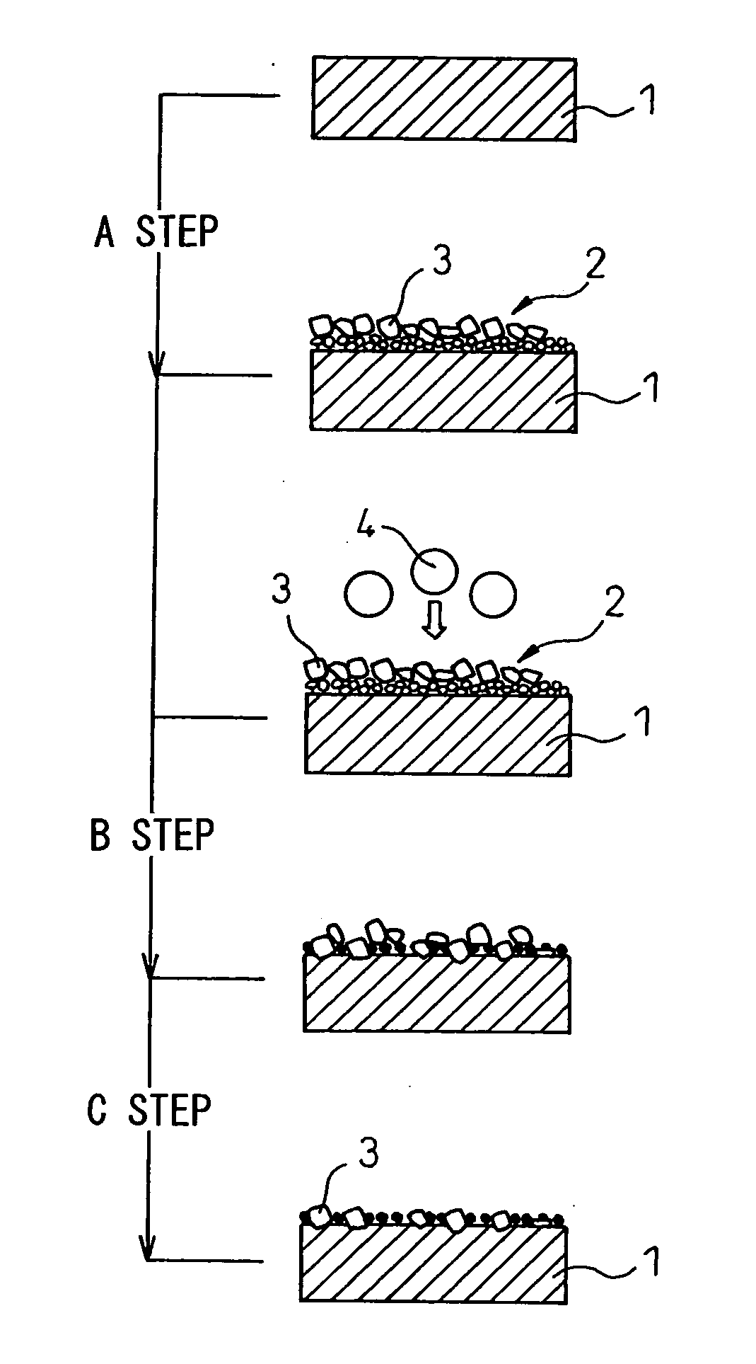
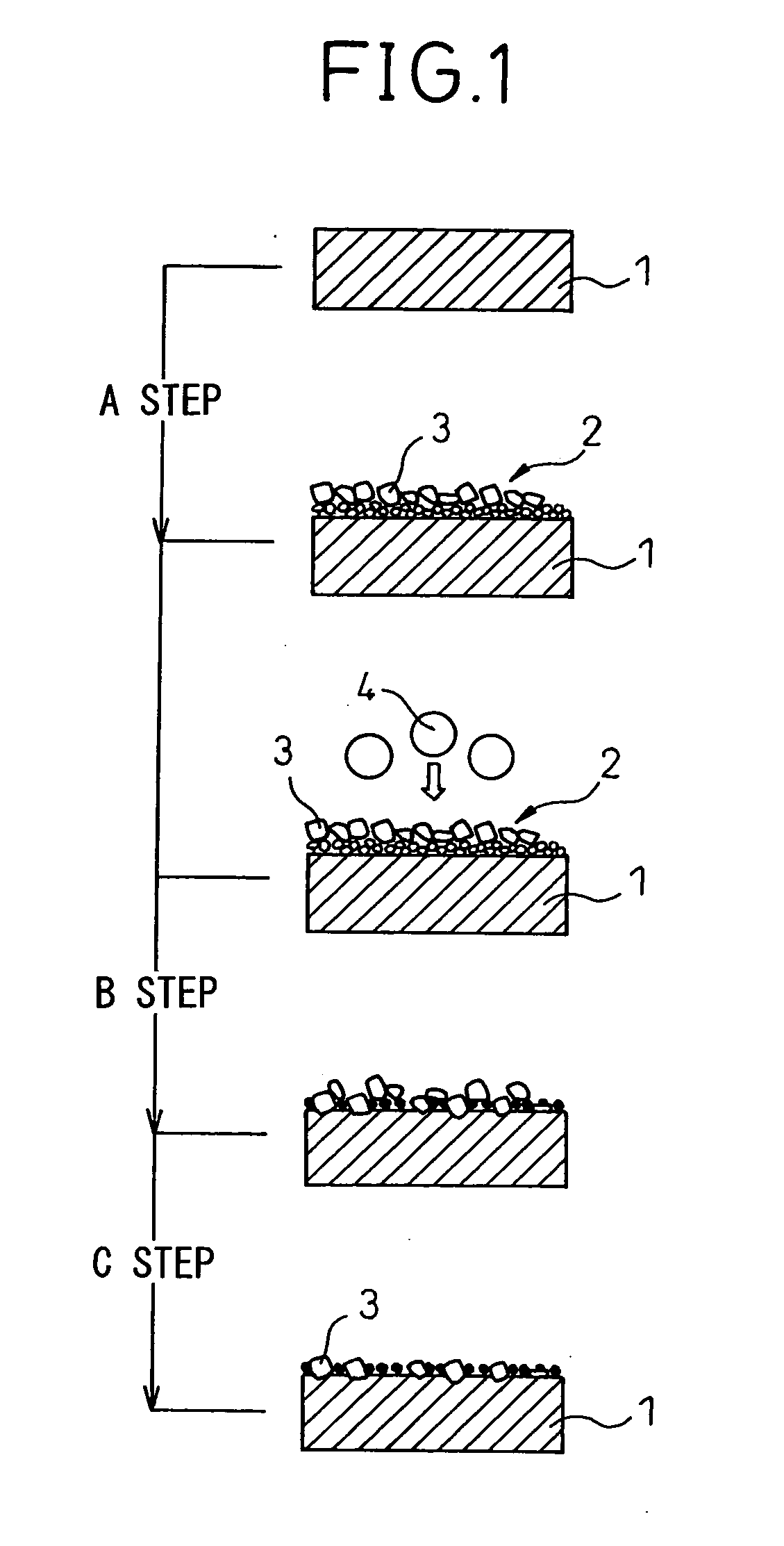
[0058]A separator-use base member 1 of outer dimensions of 150 mm×150 mm×0.15 mm (thickness) made of titanium was prepared. As conductive compound particles 3, 40 g of vanadium carbide (VC) of an average particle size of 2 μm and 600 g of an ethanol solution were charged into a tank of a not shown pressurized type coating tank apparatus having an inside diameter of 97 mm and an inside capacity of 1 liter. A stirring unit was driven to mix these and prepare a suspension. Note that the area of the surface of the titanium separator-use base member 1 to be imparted conductivity, that is, the area of one side of the separator-use base member 1 spray coated with the suspension to form a conductive compound particle-coated layer and blasted by the blast particles to driven in the conductive compound particles to anchor them, was made 100×100 mm=10,000 mm2 (100 cm2). Note that, the weights of the conductive compound particles 3 and ethanol solution show the weights charged for mixing and pr...

example 2

[0064]100 g of TaN of an average particle size of 4 μm and 600 g of an ethanol solution were charged into the tank of a pressurized type coating tank apparatus similar to Example 1 to mix and prepare a suspension. Next, the suspension in the tank was pressurized and fired from a spray gun so as to spray coat the surface of a separator-use base member 1 having the same outer dimension as Example 1 of 150 mm×150 mm×0.15 mm (thickness) and made of titanium by an amount of coating per unit area of 1.0 mg / cm2. The rest of the test conditions were the same as in Example 1.

example 3

[0065]40 g of VC of an average particle size of 2 μm and 600 g of an ethanol solution were charged into the tank of a pressurized type coating tank apparatus similar to Example 1 to mix and prepare a suspension. Next, the suspension in the tank was pressurized and fired from a spray gun so as to spray coat the surface of a separator-use base member 1 having the same outer dimension as Example 1 of 150 mm×150 mm×0.15 mm (thickness) and made of titanium by an amount of coating per unit area of 0.2 mg / cm2 and was dried. After this, using, as the blast particles used in step B of anchoring the conductive compound particles, TiN of an average particle size of 100 μm and a pressure of 0.018 MPa, the conductive compound particle-coated layer 2 formed on the surface of the separator-use base member 1 was blasted. The rest of the test conditions were the same as in Example 1.


PUM


Abstract

The present invention provides a method of treatment for imparting conductivity to a surface of a separator-use base member resulting in little distortion and superior conductive performance for a separator-use base member of a solid polymer type fuel cell made of any of a sheet of stainless steel, titanium, or titanium alloy, comprising a step of spray coating and drying on the surface of the separator-use base member a suspension prepared by mixing conductive compound particles 3 of an average particle size of 1 to 10 μm with ethanol or water so as to form a conductive compound particle-coated layer 2, a step of blasting the conductive compound particle-coated layer 2 with blast particles 4 having an average particle size of 50 to 200 μm so as to drive the conductive compound particles 3 in the inside direction of the separator-use base member 3 and anchor them there, and a step of cleaning off conductive compound particles 3 not anchored to the surface of the separator-use base member 1 at that step and impurities.

Description

TECHNICAL FIELD[0001]The present invention relates to a method of treatment for imparting conductivity to the surface of a separator-use base member of a solid polymer type fuel cell.BACKGROUND ART[0002]A solid polymer type fuel cell is a fuel cell using a polymer film having ion conductivity as an electrolyte. A solid polymer type fuel cell is structured from a plurality of basic units called “unit cells” stacked together and connected in series to generate a high voltage.[0003]A “unit cell” is comprised of a polymer electrolyte film at the inside, catalyst films made of platinum etc. sandwiching it at its two sides, and separator-use base members at the two sides of the catalyst films with current collectors made of carbon fiber (hereinafter referred to as “carbon paper”) interposed. Between one sheet of carbon paper and separator-use base member, a passage is formed for hydrogen gas. Between the other sheet of carbon paper and separator-use base member, a passage for air (oxygen)...

Claims


Application Information

Patent Timeline
IPC IPC(8): H01M2/16
CPCH01M8/0206H01M8/0208Y02E60/50H01M8/0228H01M2008/1095H01M8/021
Inventor YAMAZAKI, KEISUKEHISADA, WATARUKIHIRA, HIROSHITANAKA, KOKI
Owner SINTOKOGIO LTD
Why Eureka
Try Eureka