System and methods for purifying biological materials

a biological material and system technology, applied in the field of systems and methods for purifying fluids, can solve the problems of inability to achieve the purification effect of target nucleic acids, etc., to achieve the effect of reducing the potential for error

Inactive Publication Date: 2012-03-22
CHIRAL TECH
View PDF3 Cites 43 Cited by
  • Summary
  • Abstract
  • Description
  • Claims
  • Application Information

AI Technical Summary

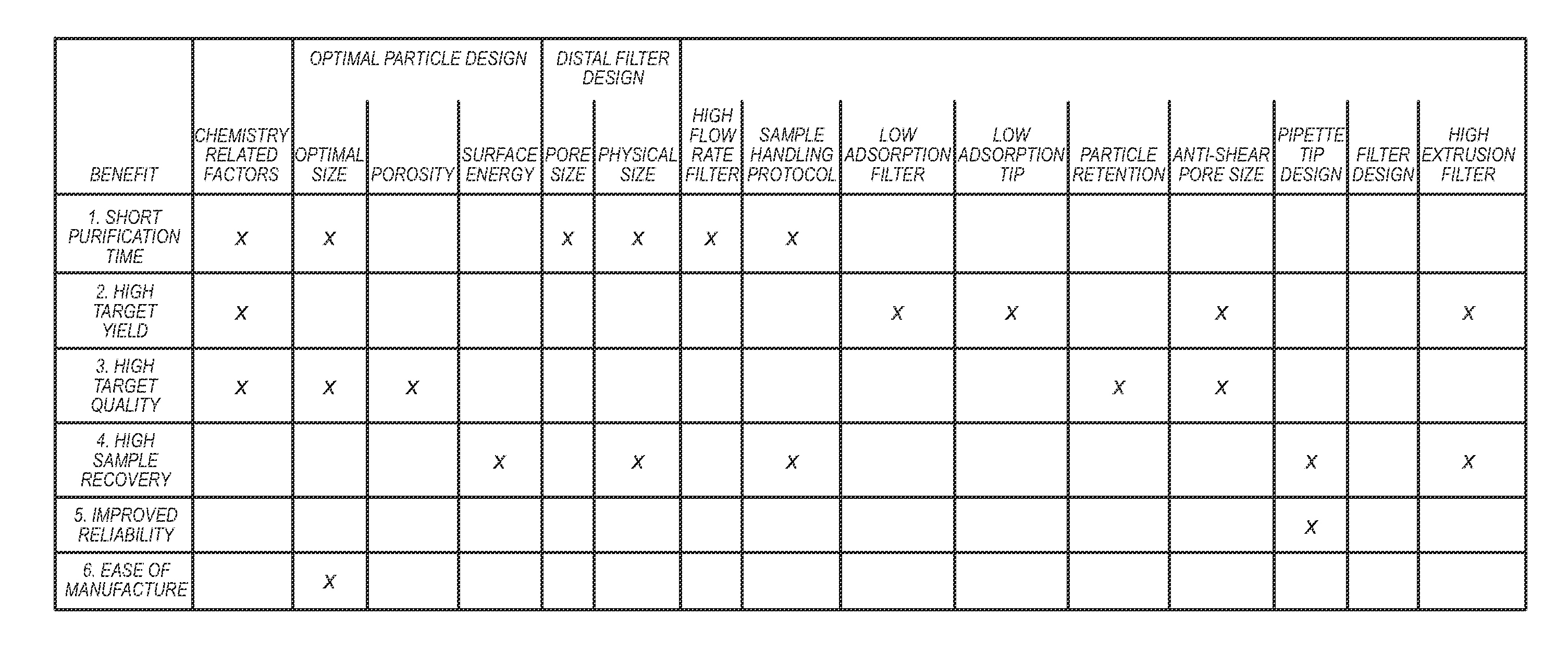
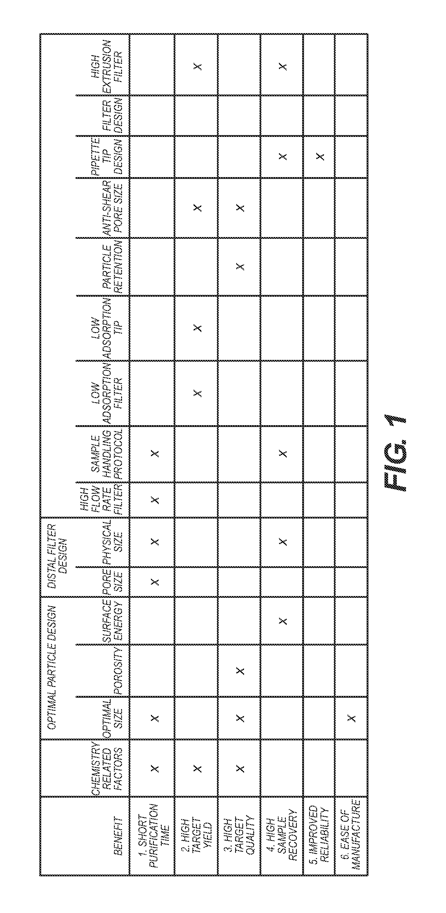
Benefits of technology

[0022]A fluid sample purification system and method is provided that is rapid, user-friendly and entails no addition or subsequent removal of analytes, reagents, or reaction products. The fluid sample purification system and method reduce the potential for error and results in a user-friendly process that takes 1 minute or less and removes over 95% of the impurities (i.e., primers and unincorporated nucleotides) while leaving ample target biomolecules for subsequent analysis. Target biomolecules for analysis can include, but are not limited to single-stranded nucleic acids such as RNA or PCR primers, double-stranded nucleic acids, such as DNA (e.g., genomic DNA, plasmid DNA) or PCR primer-dimers, nucleotides such as ribonucleotides, enzymes such as DNA polymerases, RNA polymerases, labeled probes, restriction enzymes or reverse transcriptases, dyes such as intercalating agents, water, heavy metals, toxins such as blood-borne toxins (e.g., urea or creatinine), blood components including metabolites, electrolytes, hormones or drugs, and antibodies or antigens.

Problems solved by technology

Purification of a particular DNA target from the PCR amplification mixture is necessary, for example, for effective DNA sequencing, since failure to remove impurities, such as the excess primers and nucleotides (“dNTPs”) introduced during the DNA amplification process, can interfere with sequencing chemistry and can lead to inaccurate results.
However, since enzymatic methods do not remove impurities, but rather, render them inactive, the presence of inactivated impurities in solution interferes with subsequent methods for nucleic acid quantification, i.e., the impurities still affect the UV absorbance methods that are often used to quantify nucleic acid target concentration.
As a result, quantification of target nucleic acids (e.g., DNA, RNA, plasmids, etc.) purified by enzymatic methods is limited to techniques such as gel electrophoresis, which is semi-quantitative at best.
Existing total adsorption methods begin by retaining impurities as well as target DNA onto adsorbing surfaces, such as membranes or magnetic beads, requiring multiple, complex, time-consuming and expensive chemical-mechanical processes to purify and release the desired target nucleic acid.
Existing nucleic acid purification products are often criticized by users for leaving too many impurities in the product and thus resulting in poorer test results; high cost (both purification kit purchase price and end-user labor); and for being slow and requiring substantial “hands-on” time (10-20 minutes or more per sample).
The labor intensive nature of these products drives actual purification costs well above the $1-$2 (USD) disposable costs currently required to clean up a single nucleic acid sample, and provides many opportunities where operator error can adversely affect the purification process.
Many existing sample purification processes often retain a high percentage of the fluid sample, owing in part to the use of multiple purification process steps, each of which can lose a small portion of the sample.
Confining the particles with distally and proximally placed particle retainers often creates pipette tip performance problems.
One such problem is a reduction in fluid aspirate and dispense times, due to the flow resistance created by the filters.
Another problem is the propensity of the retainer to retain sample fluid, thereby reducing sample yield.
Yet another problem is the variability in pore size within a filter, whether the filter is comprised of a ceramic or polymer frit or fragile membrane.
Still another problem with existing filter designs is inconsistent fluid flow resistance across filters in multiple pipette tips.
Still another problem with existing filter designs is high cost.
Underlying causes include low fluid flow rate due to the use of a high resistance filter as well as the use of a second filter to contain the adsorption media prior to and during use, hydrophobic adsorption media which require pre-wetting, entrapment of air with the reaction chamber, and clogging of the filters by the relatively large volume of adsorption media required
Another shortcoming is poor reliability.
Another shortcoming is inherently higher product manufacturing cost.
Underlying factors include the use of a second filter and relatively large volume of adsorption media required, which also increases retained sample fluid and increases pipette tip manufacturing cost.
Underlying causes include high fluid flow resistance caused by the porous matrix used to contain adsorption material.
Another shortcoming is potential for poor yield of target materials.

Method used


Image

  • System and methods for purifying biological materials
  • System and methods for purifying biological materials
  • System and methods for purifying biological materials

Examples


example 1

6.1 Example 1

Preferred Embodiment of Fluid Sample Purification System

[0482]This example demonstrates a preferred embodiment of the fluid sample purification system. The system comprises a distal particle retainer that has effective particle retention, minimizes resistance to fluid flow, has consistent tip-to-tip flow resistance, has faster sample processing time, minimizes retention of sample fluid, has improved product manufacturability, has reduced product manufacturing cost, and has improved sample quality.

[0483]This example describes an improved pipette filter design that can be used in the fluid sample purification system. Specific features of the filter include very low fluid flow resistance, consistent fluid flow resistance, uniform pore size, low sample retention and low cost. Unlike prior art fluid sample purification systems, the embodiment of the fluid sample purification system with this filter design has features within the pipette tip, rather than a separate filter, to...

example 2

6.2 Example 2

Fluid Sample Purification System Comprising Pipette Tip with Mixing (Reaction) Chamber

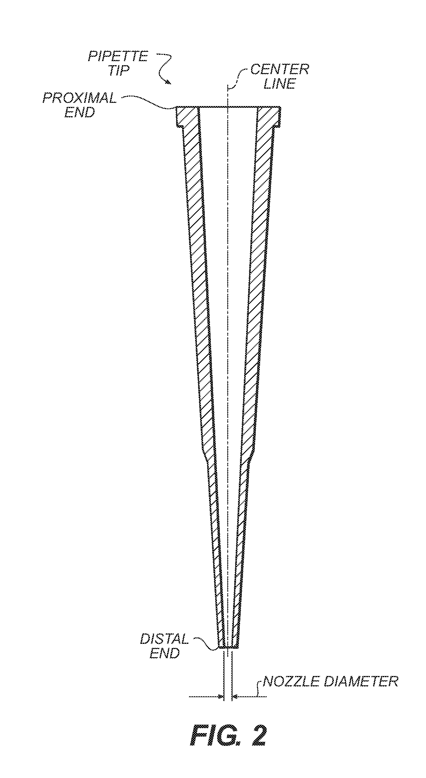
[0501]This example describes an additional embodiment of the fluid sample purification system that comprises a pipette, tip that has a different fluid mixing (or reaction) chamber design than described above. The mixing (reaction) chamber has a low slenderness ratio, which design permits more effective interaction between the aspirated / dispensed sample and adsorption materials. FIG. 40b shows pipette tip A containing loosely packed particles (not shown but similar to FIG. 2) and distal particle retainer B designed with a mixing chamber C with low height L. (FIG. 40a shows a typical prior art pipette tip configuration.) There exists a transition region which transitions nozzle diameter d to internal pipette diameter D in a very short distance. Preferably, angle β is approximately thirty degrees so as to help ensure uniform transition of fluid flow from the pipette nozzle to the larger i...

example 3

6.3 Example 3

Fluid Sample Purification System Comprising Pipette Tip with Minimum Internal Air Volume

[0505]This example describes an additional embodiment of the fluid sample purification system that comprises a pipette tip with an internally positioned piston to minimize internal volume and create higher fluid sample aspiration and dispense pressures.

[0506]This embodiment of the fluid sample purification system comprises a pipette tip and a piston that provides minimum air volume within the pipette tip. Since the air contained within the pipette tip is a compressible fluid, the more air there is in the tip, the less the pressure or vacuum can be generated within the pipette tip for a given displacement of the pipettor's piston. Since the difference in pressure between the inside and outside of the pipette tip is the motive force for moving liquid into or out of the pipette tip, a smaller pressure or vacuum differences result in a lower sample flow rates. Sample flow rate is further...


PUM

PropertyMeasurementUnit
diametersaaaaaaaaaa
diametersaaaaaaaaaa
specific gravityaaaaaaaaaa

Abstract

Fluid sample purification systems and methods are provided for isolating molecules of interest in a fluid sample. The fluid sample purification system has a housing with a distal end and distal opening adapted for the passage of a fluid and a proximal end and proximal opening adapted for passage of a fluid. A distal retainer is located inside the housing and above the distal opening. A proximal retainer is located inside the housing between the distal retainer and the proximal opening, or is located adjacent to, in contact with, or over the proximal opening. The system also comprises adsorption material, e.g., functionalized particles, inside the housing and confined between the distal retainer and the proximal retainer. The adsorption material adsorbs undesirable material while simultaneously rejecting desirable materials. Methods are also provided for isolating molecules of interest using the fluid sample purification system.

Description

CROSS-REFERENCE TO RELATED APPLICATIONS[0001]This application claims priority to and the benefit of co-pending U.S. provisional patent application Ser. No. 61 / 152,680, filed Feb. 14, 2009, entitled “Devices for Purifying Biological Materials” and Ser. No. 61 / 290,333 entitled “System and Methods for Purifying Biological Materials,” filed Dec. 28, 2009, both by Jeffrey L. Helfer and Rhiannon R. Gaborski, and each of which is incorporated herein by reference in its entirety.STATEMENT REGARDING FEDERALLY SPONSORED RESEARCH OR DEVELOPMENT[0002]The disclosed invention was made with government support under STTR grant numbers R41RR024968-01 and 2R42RR024968-02 from the National Institutes of Health. The government has certain rights in this invention.1. TECHNICAL FIELD[0003]The invention relates to systems and methods for purifying fluids. The invention also relates to systems and methods for separating molecules of interest from undesirable material.2. BACKGROUND OF THE INVENTION[0004]Dif...

Claims


Application Information

Patent Timeline
Patent Type & Authority Applications(United States)
IPC IPC(8): C07H21/00B01D43/00B82Y99/00
CPCG01N2001/4016B01L3/0275C12N15/1003G01N1/34B01L2300/0609B01L2200/0631B01L2300/0681G01N2035/1053G01N1/405
Inventor HELFER, JEFFREY L.GABORSKI, RHIANNON R.KILDAL, MAURICE A.
Owner CHIRAL TECH
Why Eureka
Try Eureka